


8
8
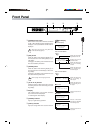
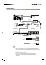
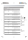
[AC IN] Power input terminal
Use the power cord supplied to connect to an AC
120 V 50 Hz/60 Hz outlet.
9
[HD-SDI IN] Video signal input terminal (BNC)
Input terminal for HD serial digital video signal.
This terminal also receives audio signal when
audio signal is embedded into HD serial digital
video signal.
Connect to the HD serial digital video signal out-
put terminal of the device outputting video signal.
0
[HD-SDI MONI OUT] Video signal output
terminal (BNC)
Output terminal for through HDTV serial digital
video signal.
For checking the video signal inputted into HD-
SDI IN video signal input terminal
9
on the rear
panel.
The output signal of HD-SDI MONI.OUT termi-
nal that has not gone through re-clock process
cannot be used as a formal SMPTE292M
(1080i/720p) standard HDTV serial digital
video signal.
!
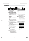
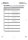
[ASI OUT] TS output terminal (BNC ×2)
TS output terminal.Encodes and outputs the
video signal inputted into HD-SDI IN video signal
input terminal
9
and the audio signal inputted
into AES/EBU IN terminal
#
.
This terminal also outputs encoded audio signal
when audio signal is embedded into HD serial
digital video signal.
#
[AES/EBU IN] Audio signal input terminal
(BNC)
Input terminal for digital audio signal (PCM or
Dolby™ Digital bitstream). Connect to the digital au-
dio signal output terminal of the device outputting
audio signal.
When using the audio signal input terminal,
set the audio input item in the Configuration
Menu to “AES/EBU”.
☞ Page 13 “Configuration Menu”
• For the audio signal to be input to AES/EBU
IN terminal, use the 48 kHz audio signal that
is synchronized with video signal.
• If Dolby™ Digital bitstream is inputted when
the Audio Format under the Initial Param
Menu is set as “MPEG”, loud sound might
be produced. Make sure that “DD-PT” is set
before inputting Dolby™ Digital bitstream.
$
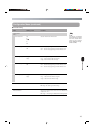
[RS-232C]Remote terminal (D-sub 9pin)
By connecting to the device for remote control, con-
trol of this unit can be performed externally.
Ⅵ
Pin assignment of RS-232C remote terminal
Rear Panel
MemoMemo
MemoMemo
MemoMemo
1
5
9
6
Pin No. Signal name Content
1
2
3
4
5
9
N.C
N.C
N.C
N.C
N.C
Received data
Tranfer speed 38.4 kbps
Data bit 8 bit
Parity None
StopBit 1 bit
Flow Control None
Transmitted data
Ground
SG
TxD
RxD
N.C
6
7
8
AC 120V
~
50 Hz/60 Hz
RS-232C
AES/EBU IN
IN
MONI
1
OUT
REF IN(D1)
ASI OUT
2
SDI
HD-
8 9 0 @ # $!
@
[REF IN (D1)] External reference
synchronized signal input terminal (BNC)
Input external reference synchronized signal.
For reference synchronized signal, use the signal
that is compliant to SMPTE259M (D1).
When using the external reference synchronized
signal input terminal, set the Sync Mode item in
the Configuration Menu to “REF”.
☞ Page 13 “Configuration Menu”
• When using the external reference synchronized
signal, keep the phase difference of external ref-
erence synchronized signal and input video sig-
nal within ±5H (1H: D1signal cycle).
(Phase zero is defined when the forth pin of D1 sig-
nal matches with first pin of input video signal.)
• Input D1 signal before turning on the power of this
unit. The encoding may not start if D1 signal is not
input when the power of this unit is turned on.
Caution
sCautions
Caution
s
Caution
sCautions
Caution
s