


Masterpage:Right+
EN 13
Filename [DR-MH30UJ_04Name.fm]
INDEX
Page 13 Monday, 12 July 2004 14:10
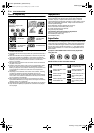
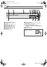
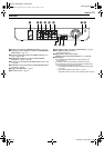
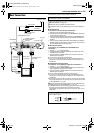
Rear View
A Antenna Connectors (ANTENNA IN/OUT) ੬ pg. 19
B Component Video Output Connectors (COMPONENT
VIDEO OUT) ੬ pg. 19
C S-video Output Connectors (S-VIDEO OUTPUT (L-1/
L-2))
੬ pg. 19, 62
D Video/Audio Output Connectors (VIDEO/AUDIO
OUTPUT (L-1/L-2))
੬ pg. 62
E S-video Input Connectors (S-VIDEO INPUT (L-1/L-2))
੬ pg. 62
F Video/Audio Input Connectors (VIDEO/AUDIO INPUT
(L-1/L-2)) ੬ pg. 62
G Region Number Label
੬ pg. 8
H AC Power Cord
੬ pg. 19
I Cable Box Control Connector (CABLE BOX)
੬ pg. 24
J AV COMPU LINK Connector*
* Not function with this unit.
K Digital Audio Output Connectors
(DIGITAL OUT (OPTICAL/COAXIAL))
੬ pg. 63, 66
L Cooling Fan
● This prevents the temperature from rising inside the unit.
Do not remove it.
● Install the unit so as not to block the area around the fan.
● The cooling fan on the rear of the unit may be activated even if
the unit is turned off in the following cases;
— In the Automatic Satellite Program Recording standby mode
(੬ pg. 50)
— when “AUTO CLOCK” is set to “ON” (੬ pg. 22)
(Set “AUTO CLOCK” to “OFF” if you mind the noise of the fan.)
PCM STREAM
AV COMPU LINK
CABLE BOX
LEFT
AUDIO
RIGHT
LEFT
VIDEO
S-VIDEO
VIDEO
S-VIDEO
L-1
L-1 L-2
L-2
AUDIO
RIGHT
COMPONENT
COAXIALOPTICAL
IN
Y
PB
PR
OUT
DIGITAL OUT
ANTENNA OUTPUT INPUT
1
L-2L-1
L-2
L-1
A E FC DB G H
J K LI
DR-MH30UJ_00.book Page 13 Monday, July 12, 2004 3:17 PM