


23
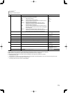
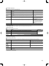
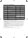
<Functions controlled by the MAKE/TRIGGER system>
Display Functions to be controlled Opening Short-circuiting
TALLY SEL Selects the color of the tally lamp Green Red
SDI 1 Changes the input to “SDI 1” Invalid Valid
SDI 2 Changes the input to “SDI 2” Invalid Valid
DVI Changes the input to “DVI” Invalid Valid
Display Functions to be controlled Invalid Valid
COMPO. Changes the input to “COMPO.” Invalid Valid
VIDEO Changes the input to “VIDEO.” Invalid Valid
3G-B.DS Selects the data stream of “3G SDI LEVEL B” DS1 DS2
DUAL LINK Turns on or off “SDI DUAL LINK” Off On
A.MARKER The area marker indication Off On
S.MARKER The safety marker indication Off On
FRAME Indication of the area of the specified aspect ratio Off On
C.MARKER The center marker indication Off On
MARK.SEL Selects the items of “MARKER” *
3
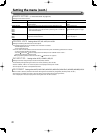
Non-“R-” items “R-” items
ASPECT Changes the aspect ratio 4:3 16:9
1:1 Displays in 1:1 mode Off On
STATUS Status display *
4
☞ “On the Status Display” on page 12
L.METER Audio level meter display *
5
TIME CODE Time code display Off On
SOURCE ID
☞ “SOURCE ID” in “INFORMATION” on page 21
*
6
WAVE FORM
Displays the wave form monitor (Normal or Difference)
*
7
VECTOR Displays the vector scope
COLOR OFF Color off Color Monochrome
SCR CHECK Screens check *
8
I/P MODE Change a mode according to the input picture *
9
MUTING Muting on/off Off On
DIMMER Change the intensity of the button lamps NORMAL DARK
−−− No function — —
*
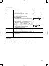
3
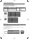
Selects which functions in “MARKER” are activated, non-“R-” items or “R-” items (☞ “MARKER” on page 15).
*
4
Displays the information shown when INPUT SELECT button of the current input is pressed (☞ “On the Status Display” on page 12). While controlling
with the MAKE system, the information is displayed only at the moment of short-circuiting.
*
5
While controlling with the MAKE system, the level meter is switched between displayed (short-circuiting) and hidden (opening). When “LEVEL METER
ch” is set to “OFF,” the level meter is not displayed (“NO EFFECT” appears). While controlling with the TRIGGER system, the pattern of the audio
channel display is switched.
*
6
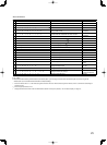
While controlling with the MAKE system, the available set-up options will be the setting value currently selected in “SOURCE ID” (“ON” or “AUTO”
[short-circuiting]) and “OFF” (opening). While controlling with the TRIGGER system, uses the same set-up option as those in the SET-UP MENU (☞
“SOURCE ID” in “INFORMATION” on page 21).
*
7
While controlling with the MAKE system, the wave form monitor and vector scope is switched between displayed (short-circuting) and hidden
(opening) regardless of the “AUTO OFF” setting in the MAIN MANU. While controlling with the TRIGGER system, the screen is switched in the same
way as when pressing the SCOPE button (☞ e on page 10). If the wave form monitor and vector scope are input at the same time, the wave form
monitor is displayed.
*
8
While controlling with the MAKE system, the screen is switched between normal screen (opening) and blue screen (short-circuiting). While
controlling with the TRIGGER system, the screen changes in the same way as when pressing SCREENS CHECK button (☞ q on page 10).
*
9
Must be controlled with the TRIGGER system. The mode changes in the order of “NORMAL” \ “CINEMA” \ “FIELD” (This function cannot be
controlled with the MAKE system).
● You cannot assign the same function to different pin terminals.
● The TRIGGER system switches each function by short-circuiting the pin terminal for about 1 second and opening it.