


Connections
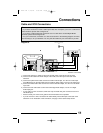
Cable and VCR Connections
11
75
Ω
(VHF/UHF)
INPUT 1 INPUT 2
S-VIDEO
VIDEO
VIDEO/Y
COMPONENT
VIDEO
OVER
AUDIO OUT
L
R
R
R
AUDIO
75Ω
(VHF/UHF)
INPUT 2
VIDEO/Y
COMPONENT
VIDEO
AUDIO OUT
L
R
R
INPUT 1
S-VIDEO
VIDEO
OVER
R
AUDIO
VCR
IN
WALL
CABLE or ANTENNA
OUT
OR
OR
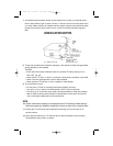
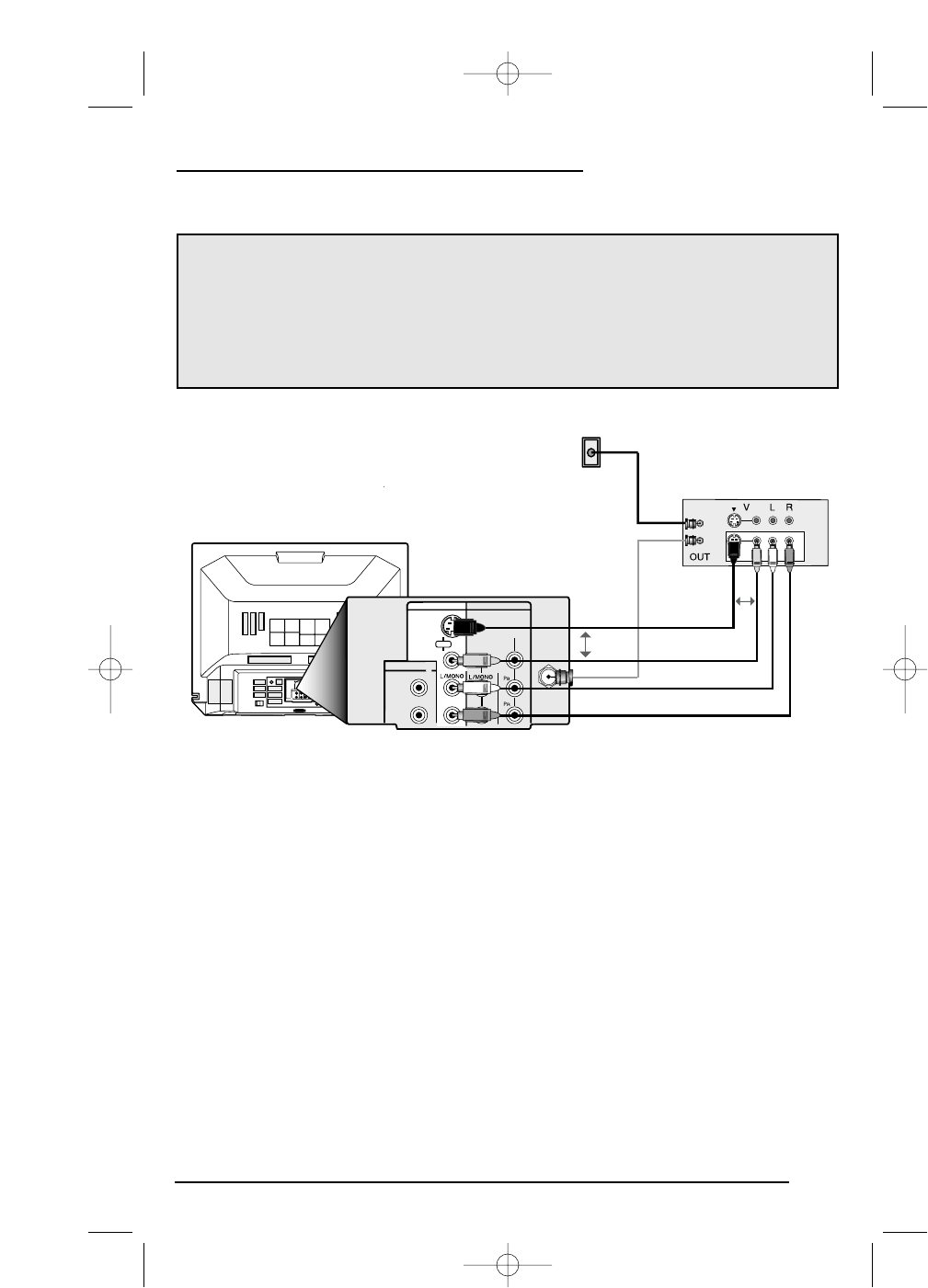
1) Connect the antenna or cable TV wire from the wall outlet, to the RF Input of the VCR.
2) Connect an RF cable from the RF Output of the VCR, to the RF Input on the back of the
television.
3) Connect the yellow video cable out from the VCR’s Video Output, in to the TV’s Video Input
jack, OR connect an S-Video cable from the VCR’s S-Video Output, to the TV’s S-Video Input.
4) Connect the white audio cable out from the VCR’s Left Audio Output, in to the TV’s Left Audio
Input Jack.
5) Connect the red audio cable out from the VCR’s Right Audio Output, in to the TV’s Right
Audio Input jack.
• If your VCR is a mono sound unit, it will have only one Audio Out jack. Connect it to the TV’s
Left Audio Input.
• Please consult your VCR’s users guide for more information on its operation.
• If you do not have a VCR, connect the RF cable directly into the RF input at the back of the
television. For an illustration of this connection, see page 8 in the Quick Setup section.
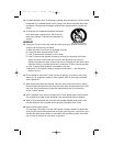
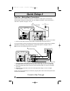
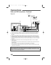
There are two basic types of antenna or cable connections:
• If you have an antenna or have a cable system that does not require you to use a cable box to
select channels, please refer to Diagram #1.
• If you have a cable system that requires the use of a cable box to access any or all the
channels, please refer to Diagram #2.
• For your convenience, connection to a VCR is also shown in the following diagrams. A VCR is
not necessary to use your television. You may omit the VCR from your connections if you wish.
Diagram #1
Illustration of AV-27D302
FD mini-IB 1/16/01 3:33 PM Page 11