


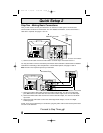
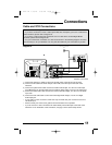
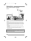
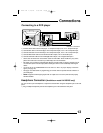
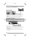
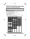
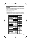
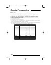
Connections
12
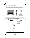
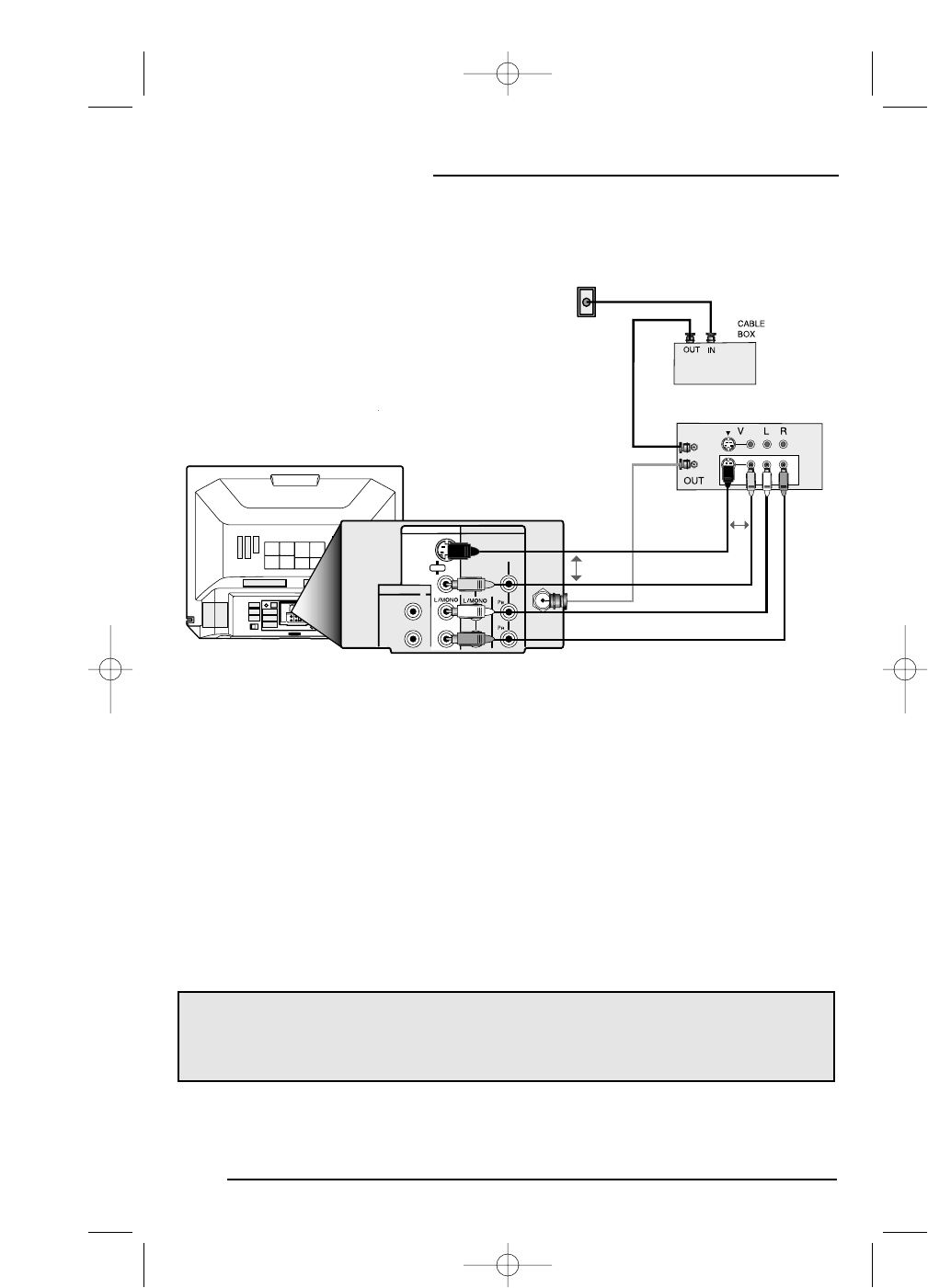
The connection diagrams are intended to show some basic general connections. Some
cable companies may require special connections to properly use your television. If you
follow these diagrams and the television does not work properly, contact your local cable
operator for more connection information.
Cable and VCR Connections - Continued
75Ω
(VHF/UHF)
INPUT 1 INPUT 2
S-VIDEO
VIDEO
VIDEO/Y
COMPONENT
VIDEO
OVER
AUDIO OUT
L
R
R
R
AUDIO
75Ω
(VHF/UHF)
INPUT 2
VIDEO/Y
COMPONENT
VIDEO
AUDIO OUT
L
R
R
INPUT 1
S-VIDEO
VIDEO
OVER
R
AUDIO
VCR
IN
OR
WALL
CABLE or ANTENNA
OUT
OR
1) Connect the antenna or cable TV wire from the wall outlet, to the RF Input of the cable box.
2) Connect an RF cable from the RF Output of the cable box, to the RF Input on the back of
the VCR.
3) Connect an RF cable from the RF Output of the VCR, to the RF Input on the back of the TV.
4) Connect the yellow video cable out from the VCR’s Video Output, in to the TV’s Video Input
jack, OR connect an S-Video cable from the VCR’s S-Video Output, to the TV’s S-Video Input.
5) Connect the white audio cable out from the VCR’s Left Audio Output, in to the TV’s Left Audio
Input jack.
6) Connect the red audio cable out from the VCR’s Right Audio Output, in to the TV’s Right
Audio Input jack.
• If your VCR is a mono sound unit, it will have only one Audio Out jack. Connect it to the TV’s
Left Audio Input.
• Please consult your VCR’s user’s guide for more information on its operation.
• If you do not have a VCR, connect the RF cable from the cable box directly into the RF input
at the back of the television.
Diagram #2
Illustration of AV-27D302
FD mini-IB 1/16/01 3:33 PM Page 12