


4
XV-N412S/GNT0044-017A/English
P
r
e
p
a
r
a
t
i
o
n
s
Connections
Before using the player, connect the player to a TV and/or
amplifier.
Before making connections
• Do not connect the AC power cord until all other
connections have been made.
• Connect VIDEO OUT of the player directly to the video
input of your TV. Connecting VIDEO OUT of the player to a
TV via a VCR may cause a monitor problem when playing
back a copy-protected disc. You may also have a monitor
problem when connecting the player to an integrated TV/
Video system.
NOTE
If your TV has an AV COMPU LINK terminal, you can use the AV
COMPU LINK function. See “AV COMPU LINK remote control
system” on page 29 for details.
Connecting to a TV
The following sections A to C describe TV connections where
only a TV is connected to the player so that you will hear audio
from the TV.
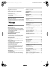
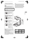
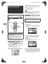
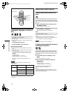
A Connecting to a conventional TV
NOTES
• Do not connect an S-video cable to the S-VIDEO output of the
player. If you do so, you will not be able to obtain correct signals
from the VIDEO jack of the player.
• If your TV has a monaural audio input instead of stereo, you
need to use an optional audio cable which converts stereo
audio output to monaural.
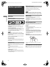
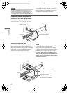
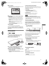
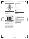
B Connecting to a TV with an S-video jack
If your TV has an S-VIDEO input, you can get better picture
quality by connecting it with the S-VIDEO output of the player
using an S-video cable instead of connecting the video input of
the TV to the VIDEO jack of the player.
NOTE
To obtain correct signals from the S-VIDEO output, do not
connect cables to the VIDEO jack and COMPONENT VIDEO
OUT jacks of the player.
Preparations
• In the following description, “TV” may be substituted with
“monitor” or “projector.”
• Terminal names used for other components may be different
from those used in the following description.
RIGHT
LEFT
AUDIO
VIDEO
IN
R
IG
H
T
L
E
F
T
C
O
A
X
IA
L
O
P
T
IC
A
L
P
C
M
/
S
T
R
EA
M
DIGITAL
OUT
AUD
IO OUT
V
ID
E
O
S
-V
ID
E
O
Y
P
B
P
R
AV
COMPU LINK
5
2
5
i
/6
2
5
i
5
2
5
p
/6
2
5
p
R
E
M
O
T
E
N
T
S
C
P
A
L
VIDEO OUT
COMPONENT
PAL NTSC
525i
/625i
525P
/625P
REMOTE
Yellow
White
Audio/video
cable (supplied)
White
Red
Ye l l o w
TV
The player
Set the PAL/NTSC selector to
“PAL” or “NTSC” to match the
color system of your TV.
(Change the selector position
in stop mode or with no disc
inserted.)
Red
Set the PAL/NTSC selector to
“PAL” or “NTSC” to match the
color system of your TV.
(Change the selector position
in stop mode or with no disc
inserted.)
Set the 525i/625i - 525p/625p -
REMOTE selector to “525i/
625i.”
RIGHT
LEFT
AUDIO
VIDEO
S-VIDEO
IN
R
IG
H
T
L
E
F
T
C
O
A
X
IA
L
O
P
T
IC
A
L
P
C
M
/
S
TR
E
A
M
DIGITAL
OUT
AUD
IO OUT
V
ID
E
O
S
-V
ID
E
O
Y
P
B
P
R
AV
COMPU LINK
5
2
5
i
/6
2
5
i
5
2
5
p
/6
2
5
p
R
E
M
O
T
E
N
T
S
C
P
A
L
VIDEO OUT
COMPONENT
PAL NTSC
525i
/625i
525P
/625P
REMOTE
TV
White
Red
The player
Red
White
Audio cable
(not supplied)
S-video cable
(not supplied)
Set the PAL/NTSC selector to
“PAL” or “NTSC” to match the
color system of your TV.
(Change the selector position
in stop mode or with no disc
inserted.)
Set the 525i/625i - 525p/625p -
REMOTE selector to “525i/
625i.”
XV-N412S(USUBUGUXUWA).book Page 4 Monday, April 5, 2004 7:40 PM