


22
Specifications (cont.)
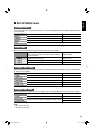
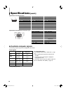
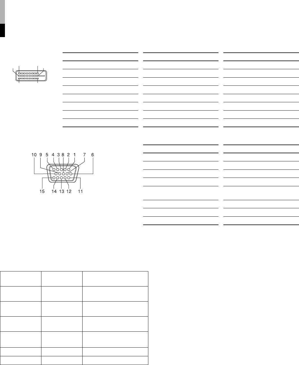
Specification of the DVI-D terminal
Pin No. Input signal Pin No. Input signal Pin No. Input signal
1
T.M.D.S Data 2–
9
T.M.D.S Data 1–
17
T.M.D.S Data 0–
2
T.M.D.S Data 2+
10
T.M.D.S Data 1+
18
T.M.D.S Data 0+
3
T.M.D.S Data 2/4 shield
11
T.M.D.S Data 1/3 shield
19
T.M.D.S Data 0/5 shield
4
NC
12
NC
20
NC
5
NC
13
NC
21
NC
6
DDC Clock
14
+5 V Power
22
T.M.D.S Clock shield
7
DDC Data
15
GND
23
T.M.D.S Clock+
8
NC
16
Hot Plug Detect
24
T.M.D.S Clock–
Specification of the RGB terminal (D-sub 15-pin)
Pin No. Input signal Pin No. Input signal
1
Red
9
+5 V
2
Green
10
GND
3
Blue
11
GND
4
—
12
DDC data
5
GND
13
Horizontal sync/
composite sync
6
GND
14
Vertical sync
7
GND
15
DDC clock
8
GND
External
GND
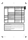
7 Available computer signals
The following computer signals can be displayed on the monitor.
Preset signals
Signal name
Screen
resolution
Vertical frequency
(reflesh rate)
For analog RGB signals:
In the following cases, perform “AUTO ADJ.” (☞ page
13)
• When inputting other signals than those listed in
this table
• If the picture of the listed signals is displayed in
wrong position or size
If “AUTO ADJ.” does not solve the problem, adjust the
items in “SIZE/POSI. ADJ. (RGB).” (☞ page 15)
VGA
640 x 350*
640 x 480
70 Hz*
60 Hz
SVGA
800 x 600*
800 x 600
56 Hz*
60 Hz
XGA
1024 x 768
1024 x 768*
60 Hz
70 Hz*
SXGA
(LM-170 only)
1280 x 1024 60 Hz
US TEXT
720 x 400* 70 Hz*
Macintosh
640 x 480* 67 Hz*
* Analog RGB signals only
1 8
9 16
17 24
03_LM170&150-EN4.indd 2203_LM170&150-EN4.indd 22 06.7.21 0:39:28 PM06.7.21 0:39:28 PM