


E
ENGLISH
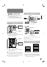
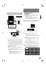
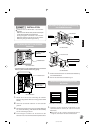
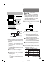
<MC-R433U connection example>
1.
Connect the power supply cable, control cable and SCSI
cable to the connectors at the rear of the MC-R433U.
Ⅵ When using the MC-8100U, the No. of the cable must
always correspond to the No. of the drive bay to which it
is being connected. If a cable with the wrong number is
connedted, it will lead to the equipment malfunctioning.
Ⅵ When using the MC-8200U/8600U, connect power sup-
ply and control cables, which lead from the side of the
MC-R433U drive bay to the drive.
Ⅵ Insert all connectors firmly.
Ⅵ SCSI cables are connected as a daisy chain connec-
tion. Each connector should be connected to the drive
positions as illustrated in the diagram.
Ⅵ Ter mi na te each point where the SCSI bus is terminated
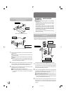
physically.
• Setting of the built-in terminators
"Procedure for Setting the DIP Switch" on page 5
• Setting of the external terminators:
The use of active terminators is recommended.
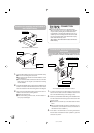
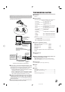
1.
TERM: Selection of the use of built-in terminators.
Ⅵ When using the built-in terminators:
• With the MC-R433U unit located at a point where
the SCSI bus is physically terminated set its TERM
ON.
• With other MC-R433U units, set their TERMs to OFF.
Ⅵ When not using the built-in terminators:
• Attach external terminators to the OUT terminals of
the SCSI connector.
• When using an external terminator, set all of the
TERMs of the MC-R433U to OFF.
Ⅵ To improve the stability of SCSI bus communications, it
is recommended to use an active external terminator.
2.
ID2, ID1, ID0: Setting of the SCSI ID No. of each drive.
Ⅵ When setting the SCSI ID No., use a number that is not
being used by other SCSI devices on the same bus.
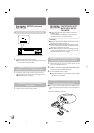
<MC-R433U rear panel>
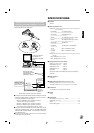
<MC-R433U DIP switch settings on the rear panel>
DVD-RAM/R drive
Library SCSI board
DVD-RAM/R drive
DVD-RAM/R drive
(Terminate.)
●
SCSI connector terminals
OUT 2:Active terminator connected.
IN 2 :Connected to the host computer's
SCSI host adapter No. 2.
OUT 1:Active terminator connected.
IN 1 :Connected to the host computer's
SCSI host adapter No. 1.
SCSI cable (Additional)
*Up to two DVD-RAM/R drives can
be connected.
SCSI cable (Standard)
Up to 6
*
1
drives can be connected.
(
*
1: Up to 4 with the MC-8100.)
SCSI-B
SCSI-D(F)
SCSI-C(E)
SCSI-A
OUT 2
OUT 1
IN 1
IN 2
SCSI connector
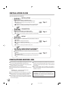
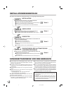
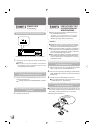
Procedure for Setting the DIP Switch
●
Set the SCSI ID of the MC-R433U and close the door
of the CD/DVD Library.
Always turn the power of the CD/DVD Library off when
the dip switches are moved.
For the details of the default factory settings, please
refer to the section "SCSI ID No. SETTING" of the
instructions from the CD/DVD Library.
SETUP
<SCSI ID No. and DIP switch settings>
*
: Factory setting.
SCSI ID No.
Switch
ID2 ID1 ID0
0 OFF OFF OFF
1
*
OFF OFF ON
2 OFF ON OFF
3 OFF ON ON
4ONOFF OFF
5ONOFF ON
6ONONOFF
7ONONON
WN
Power cable
Control cable
Slide switch
DIP switch
SCSI cable
14p
3
4p
2
3
1
NW
ON
OFF
(Factory setting)
TERM
ID 2
ID 1
ID 0
ON
1234
Procedure for Connecting the Cables to
the Back of the MC-R433U
03.7.10, 2:12 PM5