


44
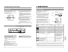
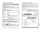
9-2 No Error Indication
9 TROUBLESHOOTING
Symptoms
No power is supplied.
Operation buttons have no effect
during recording and playback.
No picture is shown during
playback.
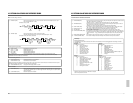
Noise appears in the picture in
the Shuttle Search mode and
Still mode.
Noise appears in part of the
playback picture.
When the cassette is played
back, the picture becomes rough
or disappears.
During playback, sound is high-
pitched and hard to hear.
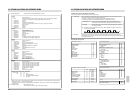
Recording is impossible.
Timer recording is working.
The clock cannot be set.
Tape running sound is heard in
the Record, Play, FF and REW
modes.
The time/date is not shown.
During recording, repeat
recording does not take place.
Camera image is not switched.
Remedies
q Connect the power cord to an AC
outlet.
q Press the REC TIMER button so that
the TIMER indication goes out.
q Release the Operation Lock mode.
Release the Operation Lock mode.
Connect the monitor correctly.
—
Adjust the tracking with the
[TRACKING+/–] button.
Tracking adjustment is not possible in
the Timelapse Play mode.
Clean the video heads. Consult your
nearest JVC dealer.
Play back the tape in the same mode
(12H or 24H) as that used for recording.
Paste a piece of cellophane tape over
the hole.
q Check again.
q Check it again.
Press the TIMER button so that the
TIMER indication goes out.
If you feel it is too noisy, install the VCR
in a rack.
q Set the clock.
q Set the <POSITION> function menu
switch to another position.
To continue repeat recording even when
the alarm recording is executed, set the
function menu switch <TAPE END
MODE> on the alarm/sensor recording
mode setting screen to REPEAT.
Causes
q Is the power cord disconnected?
q Is the TIMER indication shown?
q Is the Operation Lock mode
engaged?
Is the Operation Lock mode
engaged?
Is the monitor connected correctly?
This is not a malfunction.
q Is the tracking adjusted properly?
q Are you playing back a tape
recorded in the VHS SP (3H)
mode in the Timelapse mode?
In this case, noise appears in the
playing picture.
Dust may have accumulated on the
video heads.
Are you playing back a tape
recorded in the 12H or 24H
Timelapse mode in the VHS
Standard (3H) mode? In this case,
sound is high-pitched.
Has the cassette safety tab been
removed?
q Is the clock set correctly? Is the
timer properly programmed?
q Is the TIMER indication lit?
Is the TIMER indication lit?
This is normal.
q Is the clock set?
q Is the <POSITION> function
menu switch set to OFF?
Is the function menu switch <TAPE
END MODE> in the alarm/sensor
recording mode setting screen set to
STOP, EJECT or REW?
If so, when the tape ends during
recording in the case when alarm
recording is executed even once, it
stops or is rewound to the beginning
and stops.
Is the <CAM SW> function menu
switch set to "OFF"?
When setting the camera switching
timing, set it to "1 FIELD" or "1 FRAME".
45
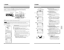
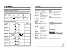
CN607
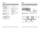
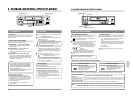
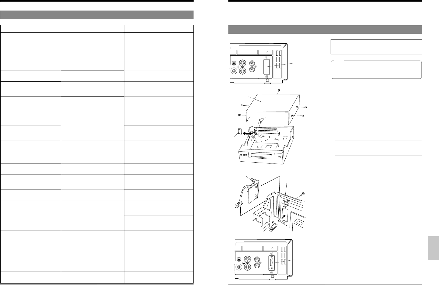
10. OPTIONAL SA-K97U RS-232C INTERFACE BOARD
Functions that can be controlled with front panel buttons and switches can also be controlled from a personal computer when
the optional SA-K97U RS-232C interface board is installed. Operation status can also be monitored on the computer.
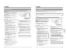
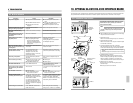
10-1. Installation of the SA-K97U
The procedure is shown below. However, to avoid
electric shock or injury, contact your local JVC
service center for details.
VIDEO
AUDIO
IN IN
OUT
OUT
REMOTE
MIC
IN
Projection sections
(2 positions)
Screws (2)
SA-K97U
RS-232C board
Positioning
holes
(2 positions)
Top cover
Screws
Plate
SA-K97U
Rear panel
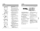
VIDEO
AUDIO
IN IN
OUT
OUT
REMOTE
MIC
IN
SA-K97U
installation
section
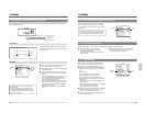
When installing this board, be careful not to injure
yourself on sharp edges and metal parts inside
the VCR.
Note:
Ⅵ Before installing the board, turn the power off and unplug
the power cord from an AC outlet.
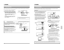
1. Detach the top cover.
Remove the 5 screws securing the top cover and lift it off.
2. Detach the plate in the VCR.
Remove the 2 screws on the rear panel. Detach the plate
from the inside of the VCR.
3. Connect the SA-K97U
’s connector to the VCR.
Insert the SA-K97U connector into the connector (CN607)
on the board in the VCR using a tool such as a pincette.
• During insertion, make sure the connector is aligned
properly.
• Press both edges of the connector to insert it securely.
4. Install the SA-K97U in the VCR.
Make sure the SA-K97U bracket is facing the correct
direction and align the positioning holes on the bracket
with the projections (2 positions) on the VCR
’s case.
Secure the bracket with the 2 screws removed in step 2.
5. Attach the top cover as before.
Attach the top cover to the VCR using the 5 screws
removed in step 1.
Make sure you use the correct screws.