


50
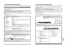
10. OPTIONAL SA-K97U RS-232C INTERFACE BOARD
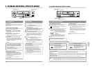
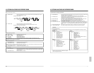
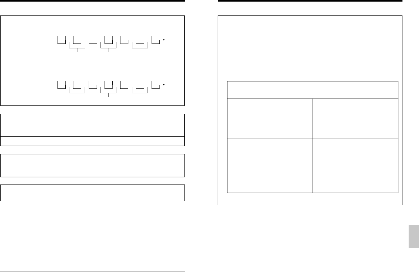
5Date and time setting commands
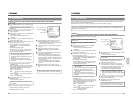
(1) DATE SET (8EH) : Set the current date (month, day, year) for the VCR. After this command (8EH) is sent, input 1-
byte numerical data (30H
— 39H).
(Example) June, 30, 1998
(2) TIME SET (8FH) : Set the current time (hour, minute, second) for the VCR.
After this command (8FH) is sent, input 1-byte numerical data (30H
— 39H).
(Example) 15 hours, 29 minutes, 59 seconds
TXD
8EH
RXD
0AH
Time
30H
0AH
36H
0AH
33H
0AH
30H
0AH
39H
0AH
38H
0AH
Month Day Year
TXD
8FH
RXD
0AH
Time
31H
0AH
35H
0AH
32H
0AH
39H
0AH
35H
0AH
39H
0AH
Minute SecondHour
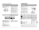
5Timer programming commands
(1) PRG/CLK (62H) : Engagestimer programming mode.
(2) SHIFT → (–) (64H) : Selects setting items. (
–)
SHIFT ← (+) (63H) : Selects setting items. (+)
(3) SET – (66H) : Sets data selected with SHIFT.
SET + (65H) : Sets data selected with SHIFT.
(4) CANCEL (67H) : Cancels program data in timer programming or engages the Cancel Program mode.
Setting procedure is the same as when using the VCR controls. Be sure to transmit commands 1 byte at a time with
“ACK” (0AH)
confirmation from the VCR after each transmission.
5On-screen setting command
(1) ON SCREEN ON (70H) : Activates time/date on-screen indication.
ON SCREEN OFF (71H) : Deactivates on-screen indication.
Setting procedure for the following command (2) is the same as when using the VCR controls. Be sure to transmit commands 1 byte
at a
time with “ACK” (0AH) confirmation from the VCR after each transmission.
(2) ON SCREEN SELECT (74H) : Changes the time display position on screen.
5Other commands
(1) AL/PL RESET (E1H) : When transmitted during alarm recording, the recording mode switches back to the previous mode.
The VCR’s “AL” indication goes off. Transmit again after
“AL” indicator goes off to reset the alarm/
power loss memory.
(2) COUNT RESET (E2H) : Resets the tape counter to
“0000”.
51
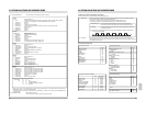
10. OPTIONAL SA-K97U RS-232C INTERFACE BOARD
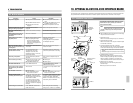
2-3 Commands for VCR status verification
(1) DATE SENSE (BEH) : The VCR returns the currently set month, day and year as 6 bytes. Each byte has a value of 30H to
39H. 30H corresponds to 0 and 39H to 9.
(Example: For June. 14, 1998, the VCR returns 30H, 36H, 31H, 34H, 39H and 38H.)
(2) TIME SENSE (BFH) : The VCR returns the currently set hour, minute and second as 6 bytes. Each byte has a value of
30H to 39H. 30H corresponds to 0 and 39H to 9.
(Example: For 15:30:45, the VCR returns 31H, 35H, 33H, 30H, 34H and 35H.)
(3) COUNT CODE (D0H) : VCR returns the counter data beginning with the 4th digit from the right in 4 bytes. ASCII codes
“30H – 39H” correspond with the numbers
“0 – 9” (eg: 1234: 31H, 32H, 33H, 34H).
(4) DEVICE TYPE (D1H) : VCR returns the last 4 characters of the SR-L910 model name in ASCII code.
L: 4CH, 9: 39H, 1: 31H, 0: 30H
(5) VTR INQ (FBH) : Used to make sure that the connected unit is the VCR. The VCR will return
“ACK” (0AH).
(6) PL/AL COUNT SENSE (D5H) : VCR will return a total of 6 bytes. The first 3 bytes show the number of alarm inputs in 3 digits and
the last 3 bytes show the number of power losses in 3 digits. ASCII codes
“30H – 39H” correspond
with the numbers
“0 – 9” (eg: 123 alarm inputs and 45 power losses: 31H, 32H, 33H, 30H, 34H,
35H).
(7) HOUR METER SENSE (D2H) : VCR returns the hour meter data in 5 bytes. (eg: 12345 hours: 31H, 32H, 33H, 34H, 35H).
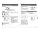
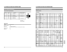
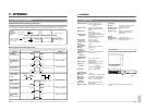
(8) TL STATUS SENSE (D6H) : VCR returns Timelapse mode data in 6 bytes. The contents of each byte are as follows:
1st/2nd byte
Recording/playback mode
Correspondence of the code and the mode is the same as that described in
“2-2 Recording/playback mode setting commands
(2) MODE (7EH)
”.
3rd byte 5th byte
Conditions of each setting Settings status
BIT Status when BIT is
“1”.
BIT Status when BIT is
“1”.
0 Not difined. Always 0. 0 REMOTE is ON.
1 Power is ON. 1 SUMMER TIME is ON.
2 Auto REC mode is ON. 2 INDEX SKIP.
3 Auto rewind mode is ON. 3 TIMER ALARM OFF.
4 Operation lock is ON.
*
4 NOISELESS PLAY ON.
5 Series recording is ON. 5 B/W mode (forced Black and White mode) ON
6 Tape end buzzer is ON. 6 CAM SW WIDTH 20msec.
7 Alarm buzzer is ON. 7 Always 0.
4th byte 6th byte
Conditions of each setting Types of warnings
BIT Status when BIT is
“1”.
HEX.Data Types of warnings
0 Alarm recording is in progress. 0 No abnormality
1 ALARM REC function is ON. 1 Loading error
2 Not defined. Always 0. 2 Unloading error
3 Sensor recording is ON. 3 Supply reel error
4 External recording function is ON. 4 Drum error
5 Always 0. 5 Take-up reel error
6 Index search mode is ON. 6 Capstan error
7 Warning buzzer is ON. 7 Cassette eject error
8 Not defined.
9 Recording check error
A Battery backup error
B Input signal error
*
Operation with commands from the RS-232C is accepted
even in the Operation Lock mode.