


DM-9090 (En)
10
R
L
SYSTEM
CONTROL
PLAY
OUT
OPT.COAX.
REC
IN
3 COAX.1 COAX. 2 OPT.
D I G I T A L
L I N E
PLAY
OUT
REC
I N
R
L
SYSTEM
CONTROL
SYSTEM
CONTROL
DIGITAL
OUTPUT
L
R
IN
OUT
PLAY
MD/DAT
REC
DIGITAL AUDIODIGITAL AUDIO
COMPACTCOMPACT
PHONES
OPTICAL
COAXIICAL
REC
IN
3 COAX.2 OPT.
DIGITAL
1 COAX.
PLAY
OUT
OPT.COAX.
REC
IN
3 COAX.2 OPT.
DIGITAL
1 COAX.
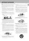
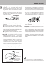
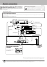
System connections
Make connection as shown below. When connecting the
related system components, refer also to the instruction
manuals of the related components.
Caution: Do not plug in the power lead until all connections
are completed.
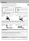
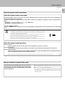
1. Connect all cords firmly. If connections are loose, there could be loss of sound or noise produced.
2. When plugging and unplugging connection cords, be sure to first remove the power cord from the AC outlet. Plugging/unplugging
connection cords without removal of the power cord can cause malfunctions or damage to the unit.
Malfunction of microprocessor
If operation is not possible or erroneous display appears even
though all connections have been made properly, reset the
microprocessor referring to “In case of difficulty”.
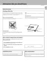
Q
Caution regarding placement
To maintain proper ventilation, be sure to leave a space around the unit (from the largest outer dimensions including projections) equal to, or greater
than, shown below.
Left and right panels: 10 cm, rear panel: 10 cm
÷When connecting the audio cords (cords with pin plugs on each end), insert
the white plugs into the L (Left) jacks and red plugs into the R (Right) jacks.
DM-9090
DIGITAL input / output jacks
(OPTICAL)
Remove protective caps
from digital input/output
jacks before use.
Remove cap.
System control cord
(CD player optional)
CD player (optional)
MD recorder (optional)
Audio cords
(DM-9090 optional)
Optical fiber cable
(DM-9090 optional)
Optical fiber cable
(optional)
System control cord
(DM-9090 optional)
TO WALL AC
OUTLET
Integrated amplifier (optional)
Except for U.S.A., Canada
Notes
Notes