


62
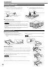
Installation
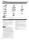
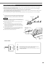
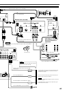
Connecting the ISO Connector
The pin arrangement for the ISO connectors depends on the type of vehicle you drive. Make sure to make the proper
connections to prevent damage to the unit.
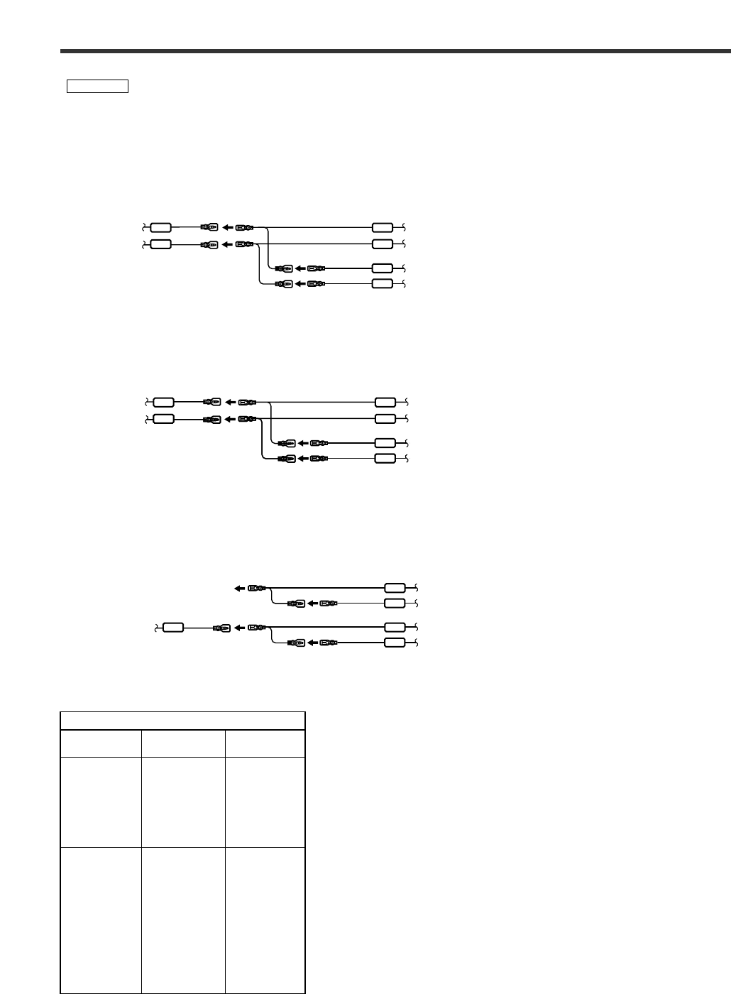
The default connection for the wiring harness is described in 1 below. If the ISO connector pins are set as
described in 2 or 3, make the connection as illustrated.
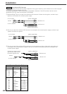
2WARNING
BATT
ACC ACC
ACC
BATT
BATT
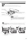
Receiver unit
Monitor unit
Vehicle
Ignition cable (Red)
Battery cable (Yellow)
A–7 Pin (Red)
A–4 Pin (Yellow)
BATT
ACC BATT
BATT
ACC
ACC
BATT
ACC
Vehicle
Ignition cable (Red)
Battery cable (Yellow)
A–7 Pin (Red)
A–4 Pin (Yellow)
Ignition cable (Red)
A–4 Pin (Yellow)
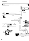
1 (Default setting) The A-7 pin (red) of the vehicle's ISO connector is linked with the ignition, and the A-4 pin
(yellow) is connected to the constant power supply.
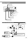
2 The A-7 pin (red) of the vehicle's ISO connector is connected to the constant power supply, and the A-4 pin
(yellow) is linked to the ignition.
3 The A-7 pin (red) of the vehicle's ISO connector is not connected to anything, whilst the A-4 pin (yellow) is
connected to the constant power supply (or both the A-7 (red) and A-4 (yellow) pins are connected to the
constant power supply).
ACC
ACC
BATT
BATT
BATT
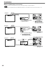
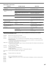
Connector Function Guide
Pin Numbers for
ISO Connectors
Cable Colour Functions
External Power
Connector
A–4
A–5
A–6
A–7
Speaker
Connector
B–1
B–2
B–3
B–4
B–5
B–6
B–7
B–8
Yellow
Blue/White
Orange
Red
Purple
Purple/Black
Gray
Gray/Black
White
White/Black
Green
Green/Black
Battery
Power Control
Dimmer
Ignition (ACC)
Rear Right (
+)
Rear Right (–)
Front Right (+)
Front Right (–)
Front Left (+)
Front Left (–)
Rear Left (+)
Rear Left (–)
Receiver unit
Monitor unit
Receiver unit
Monitor unit
Battery cable (Yellow)
Vehicle
Connect to a power source
that can be turned on and
off with the ignition key.