


95
Chapter
2
File
Menu
900
910
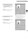
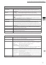
File – Import – Digitizer – Step Scan (When VIVID 900/910 is Selected)
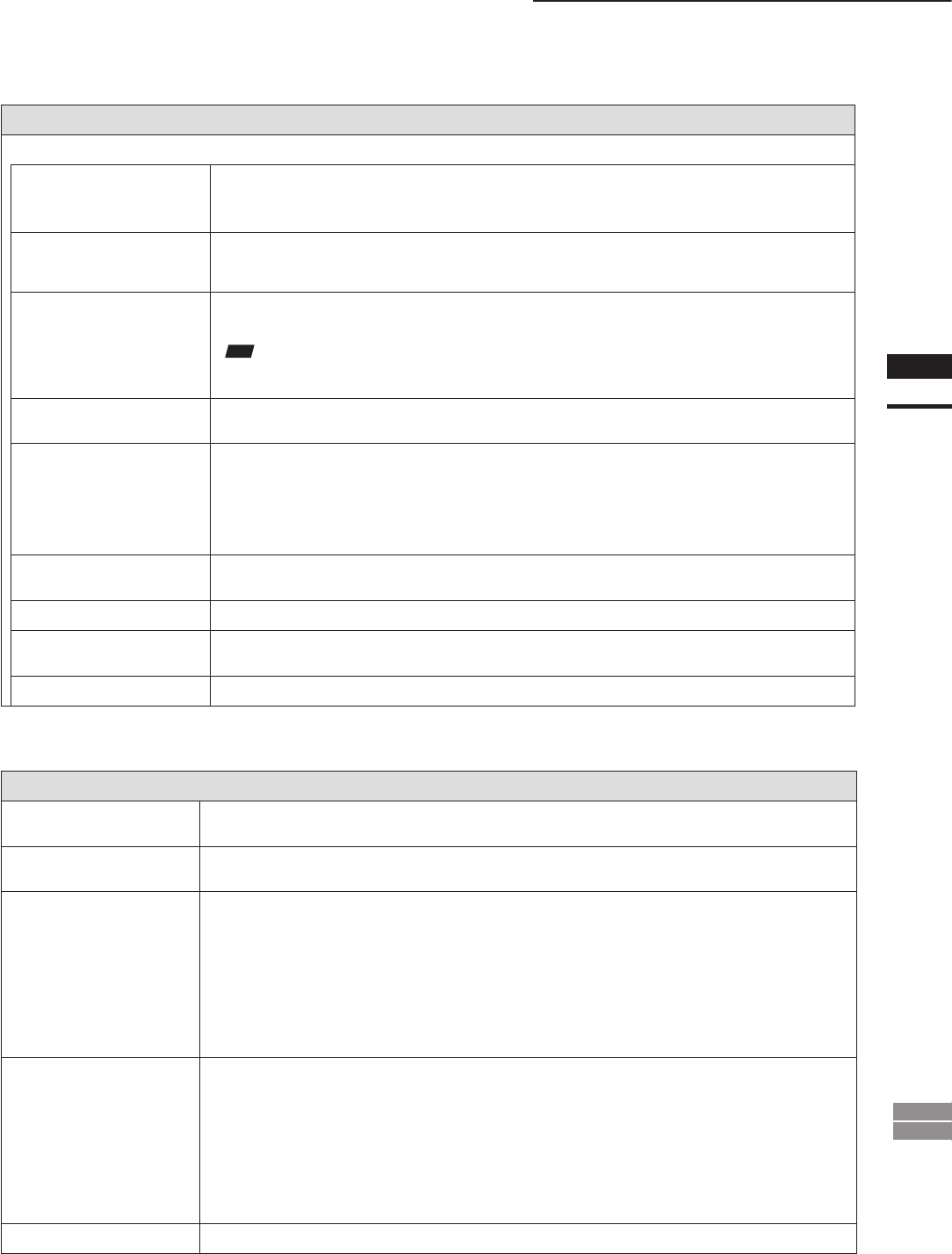
Parameters for [File-Import-Digitizer-Step Scan] Dialog Box
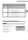
Hardware Tab
Auto SCSI ID
Check this checkbox if you want the program to automatically check SCSI connections for
VIVID units. If this checkbox is not checked, the program will recognize VIVID units at specied
SCSI IDs only.
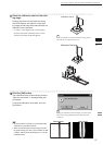
Mounted • Vertical : Check this checkbox if using the VIVID unit in vertical orientation.
• Horizontal : Check this checkbox if using the VIVID unit in horizontal orientation.
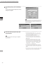
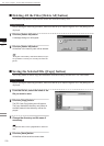
Apply
To change the rotation stage being controlled: Select the appropriate serial port and rotation
stage, and then click [Apply].
Note
IfconnectingtoaSKIDS-60YAWunit,select“CSG-602R(Ver.1.0)”fromthepull-downmenu.Ifcon-
nectingtoaSKIDS-60YAW(Ver.2.0)unit,select“CSG-602(Ver.2.0)”.
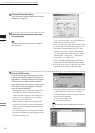
Rotation Step
Sets the rotational step, in degrees. You can set this to 90, to 60, or to “Other”. If you select
“Other”, you can proceed to enter your own custom setting.
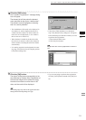
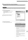
Current angle
Selects the scanning step (the scan angle). When the dialog box opens, the setting is “0”.
To change the setting, left-click on the angle to open the pull-down menu, and then enter the
scanning step (angle) that you wish to use. If you enter an angle that was already used for a scan
and then proceed to click the [Scan] button, the new scan data will overwrite the previous data
for that angle.
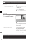
Check Scanning area
TurnstherotatingstagethroughtheanglesetbytheRotationStepsetting,whiledisplaying
amonochromeimageinthepreviewwindow.
Bench Top Frame Set
Checking this item enables the [Auto Scan] function.
Auto Scan
The program automatically scans over the angle set by the [Rotation Step] setting, and automati-
cally reads in the resulting camera data.
Chart File Data
Displays the information ([Lens Type], [Mode], [Distance], [Setting]) of the saved calibration data.
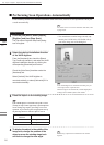
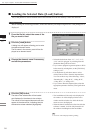
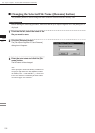
Parameters for [File-Import-Digitizer-Step Scan-Convert] Dialog Box
Reduction Rate
Selects the reduction rate to be applied when importing the data. You can select any of the follow-
ing: “1/1”, “1/4”, “1/9”, “1/16”, or “No polygon”.
Fill Holes
Selects whether the programs ll in holes when importing the data. If the setting is “On”, the pro-
gram will automatically generate points to ll in holes left by missing data.
Remove
Selects which the data the program excludes when carrying out the import. Select from an of the
following: “None”, “Boundary (B.)”, “5deg. & B.”, “10deg. & B.”, “15deg. & B.”, or “20deg. & B.”
None: Removal is not carried out when importing the data.
Boundary(B.): The program removes boundary points.
5deg. & B.,10deg. & B., 15deg. & B., 20deg. & B.:
The program removes boundary points, and also removes polygons within the
specied angular range (5°, 10 °, 15°, or 20°) to the view vector
Filter
None: The program does not perform ltering when importing the data.
Noise Filter (N.F.): When importing the data, the points that appear to be noise will be corrected
according to other data.
High Quality
(H.Q.)
: The program lters out unreliable data. (Effective only when importing data
that was scanned using the VIVID 910.)
H.Q & N.F.: Applies both noise lter and high quality lter. (Effective only when importing
data that was scanned using the VIVID 910.)
Save CDM
Save the images as camera data.