


Locating the Switchplate
A switchplate has been provided to serve as the hub of the
TracVision 6 wiring (with the exception of the RF cable, which
will be connected to the IRD). The switchplate includes an
On/Off switch and a DB9 maintenance port for easy access to the
antenna unit’s software and diagnostics. Follow the steps below
to select and prepare the switchplate mounting location.
1. Select a location to mount the TracVision 6
switchplate. It should be installed in a dry, flat
location within reach of the cables that will
connect to the antenna unit and allowing easy
access to the front panel.
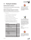
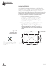
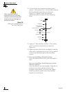
2. Once you’ve decided on a suitable location, create
a panel cutout in the mounting surface.
Figure 2-3 illustrates the mounting dimensions
and a template has been provided in Appendix B.
The connecting cables will be routed through this
cutout.
54-0166
14
TracVision 6 Technical Manual
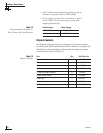
3.82"
(97 mm)
.32" (8 mm)
2.36"
(60 mm)
.16" (4 mm)
3.19"
(81 mm)
2.05"
(52 mm)
Panel Cutout
3
/32" (2.5 mm) dia
Figure 2-3
Switchplate Panel
Cutout Dimensions
A full-scale panel cutout template
has been provided in
Appendix B
on page 73.