


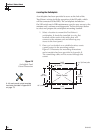

9. Clean the mounting surface where the foam seal
will be placed. Remove the paper backing from the
foam seal to expose the contact cement, then lay
the foam seal in place, adhesive side down, and
press down firmly to bring the adhesive into full
contact along the mounting surface.
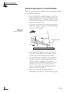
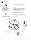
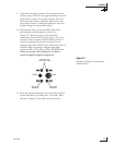
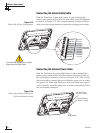
10. Connect the data, power, and RF cables from
belowdecks to the baseplate as shown in
Figure 2-7. Turn the power and data cable
connectors down until locked in place; don’t use
excessive force. Connect the RF cable(s) with a
7
⁄16"
wrench, applying 30 pounds of torque. If you
connect more than one RF cable, label both ends of
each RF cable to match its antenna baseplate
connector (RF1, RF2, RF3, or RF4). Do NOT use
teflon gel on the cable fittings as it reduces
signal strength at higher frequencies.
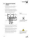
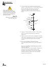
11. Place the antenna baseplate over the holes drilled
in the foundation, ensuring the “Forward” label
(shown in Figure 2-5) points toward the bow.
Installation
54-0166
17
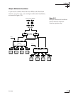
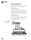
Figure 2-7
Baseplate Connector Assignments
(Bottom View)
DataPower
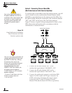
Single IRD
Installation
Second IRD
Installation
Used only with
Quad-output LNB