


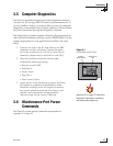
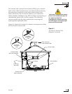
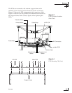
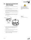

The PCBs are mounted to the antenna support frame with
machine screws and are interconnected by Molex connectors.
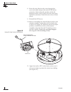
Figure 4-3 shows the PCB arrangement and connectors, while
Figure 4-4 shows how the printed circuit boards are mounted to
the support frame. Refer to these figures when replacing the
PCBs.
Maintenance
54-0166
55
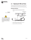
MAIN PCB
Azimuth Motor
Elevation Motor
Cable Wrap
RF PCB
Antenna Gyro
Azimuth Limit
Switch
Fuses
Power/Data
to Main PCB
RF Connectors
to RF PCB
Elevation Limit
Switch
Figure 4-4
PCB Mounting (Top View)
RF PCB Main PCB
Support Frame
Figure 4-3
PCB Connector Locations
(Rear View)