


2-7
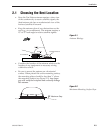
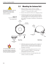
Installation
54-0157 Re
v
.
H
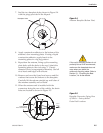
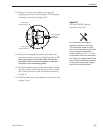
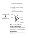
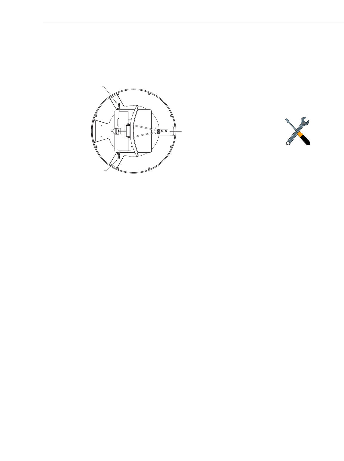
13. Remove the nuts and washers securing the
shipping restraints to the baseplate. The shipping
restraints are pictured in Figure 2-8.
14. Remove the shipping restraints and replace the
nuts and washers into their original positions.
All
nuts and washers removed in Step 13 must be
reinstalled. These nuts and washers secure the
baseplate to the mounting plates.
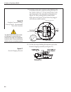
15. Place the radome onto the baseplate (labels facing
the sides of the vehicle) and secure in place using
the 8 pan head screws and flat washers removed
in Step 10.
16. Drill the cable access hole (marked in Step 4) in the
vehicle’s r
oof.
R
otating Plate
S
hipping Restraint
R
otating Plate
Shipping Restraint
Forward Shipping
R
estraint for
LNB Bracket
Figure 2-8
TracVision R5/R4 Shipping
Restraints (Top View)
Do not discard the shipping
restraints, washers, or the nuts.
They should be saved for future
use in case the antenna unit needs
to be removed and shipped to
another location. Four
1
⁄4˝ x
5
⁄8˝ hex
head screws have been provided in
the kitpack for shipping as the bolts
used to hold the shipping restraints
during initial shipping are integral
parts of the mounting plates.