


2-11
Installation
54-0157 Re
v
.
H
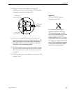
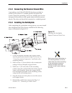
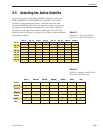
2.3.3 Connecting the Receiver Ground Wire
A grounding wire (Cable #32-0583-50) has been provided to
connect your receiver to a suitable ground and protect the
system. Attach the grounding wire to any suitable screw on the
rear panel of the receiver with a good contact with the receiver
chassis. The other end should be connected to a suitable ground.
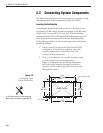
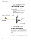
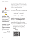
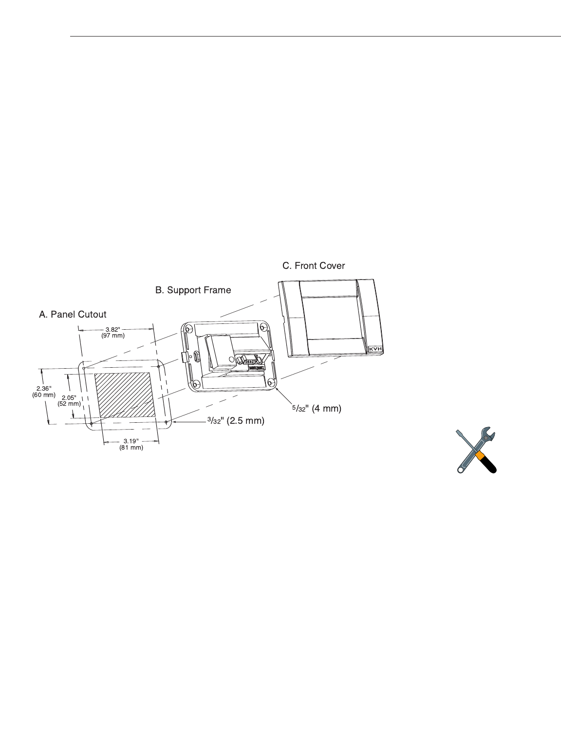
2.3.4 Installing the Switchplate
After completing the switchplate wiring process, you must install
the switchplate itself. This process, detailed in the following
steps, is illustrated in Figure 2-13.
1. Fit the switchplate assembly and support frame
into the panel cutout made in Step 2 of
Section 2.3,
“Connecting System Components,”
and flush to the
mounting surface.
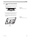
2. Drill out four
5
⁄32" (4 mm) holes in the countersunk
settings in the switchplate support frame.
3.
Drill four
3
⁄32" (2.5 mm) holes in the mounting
surface using the countersunk holes in the support
frame as the
template
. Secur
e the support frame
and switchplate assembly to the mounting surface
using four #6 self-cutting scr
ews.
4. Snap the front cover into place to cover the screws
and support frame.
5.
Reinstall the vehicle fuse r
emoved in Step 1 of
Section 2.3.2, “Connecting to V
ehicle Power
.”
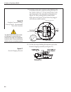
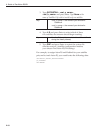
Figure 2-13
Mounting the Switchplate
Support Frame and Front Cover
Before securing the switchplate to
the mounting surface, be sure to
strain-relieve the wires connecting
to the switchplate connectors.
Several tie-wraps have been
provided to aid in strain-relieving
the wires.