


5-6
A Guide to TracVision R5/R4
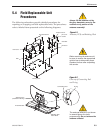
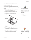
7. The PCB is mounted to the r
otating plate with
9 pan head scr
ews. Remove the screws and PCB.
8. Reverse this process to install the replacement
PCB. Reinstall all cable connectors removed in
Step 6.
9.
(T
racVision R5 only)
Carry out all calibration
pr
ocedures for the antenna gyro
(Section 5.4.3).
10. Reinstall your preferred satellites as detailed in
Section 2.5.1, “Installing Your Selected Satellites.”
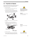
5.4.2 RF Detector/DVB Decoder
Estimated Time to Repair:
1
⁄2 hour
The RF Detector PCB receives operating voltages from both the
CPU board and the receiver (via the RF cable). Ensure that all
power is turned off before proceeding.
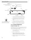
1. Remove the 4 RF board cover screws and washers
from the RF board cover.
2. Remove the RF board cover.
3.
Remove the 2 RF connectors from the coaxial
fittings on the RF boar
d. Tag the cables to ensure
that they ar
e returned to the same connectors.
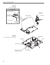
4. Remove the 2 Molex connectors from the RF board
(J3 and J1)
– Fig. 5-6.
When replacing the PCB cover, be
careful not to pinch any cables.
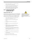
RF Board
PCB
J3
J
1
RF Connector to IRD
R
F Connector to LNB
Fuses
J5
J11
J9
J2 J1
J
4
Gyro
(
TracVision R5 only)
RF Board
L
imit Switches
Power/Data
Elevation Motor Azimuth Motor
F
igure 5-6
PCB and RF Detector Board
Connector Locations