


36
206-4186
AUDIO IN
(RGB/DVI)
RS-232C IN
(SERVICE ONLY)
.....
....
VIDEO
L/MONO-AUD
IO-R
AV IN 1
TV-LINK
CFG
GAME
CONTROL/
MPI
REMOTE
CONTROL
OUT
COMPONENT IN
R
L
PB
Y
P
R
VIDEO
AUDIO
ANTENNA IN
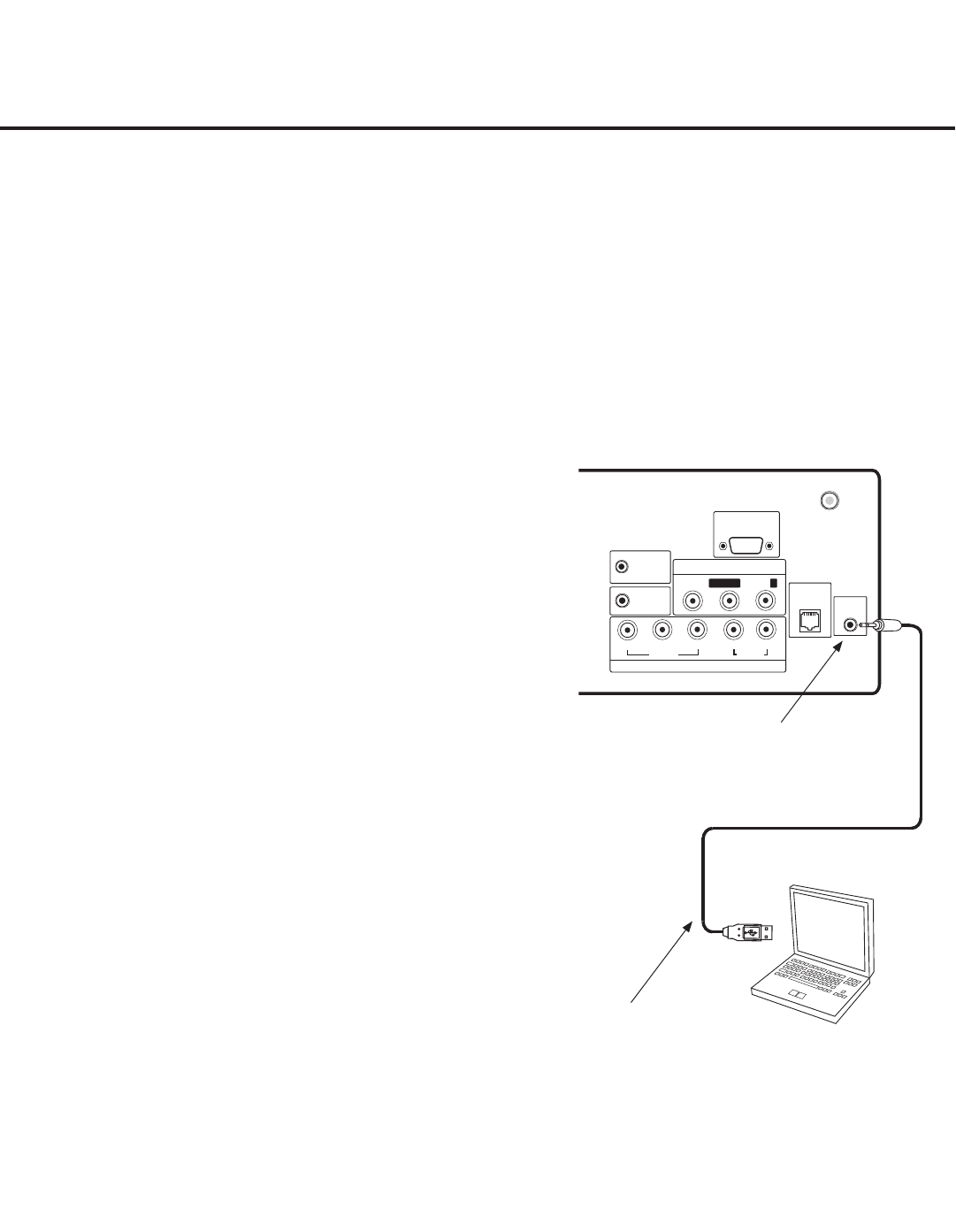
Laptop
PC
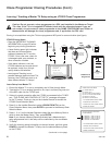
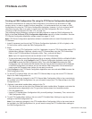
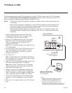
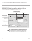
The following steps outline local FTG configuration of individual TV EBLs using a direct PC-to-TV connection.
Refer to the Free-To-Guest (FTG) Configuration Application manual for further information. See also FTG
Device Configuration Application sample screens on pages 37 to 40.
Notes: • FTG Device Conguration Application software is available online at: www.LGcommercial.com/
FTGsoftware.
• If the TV CPU is already in FTG Mode, you cannot use this procedure to make changes to the
FTG Channel Map and FTG Installer Menu settings. Instead, refer to and use the processes
described on pages 32 and 33 to recongure the TV CPU.
• If the preceding condition applies, but you wish to switch the TV to FTG Mode via EBL, refer
to Reference section, “Resetting Factory Defaults on the TV(s),” for further information before
proceeding.
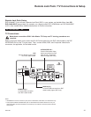
TV-LINK CFG
Use for direct PC-to-TV
FTG configuration.
USB-to-TTL Serial Cable
Required for direct PC-to-TV
FTG configuration.
FTG Mode via EBL
Notes:
• ANTENNA IN connector located on jack panel on
26LD320H, 26LD340H, and 26LD345H only.
• Dual-purpose GAME CONTROL/MPI port on
26LD320H and LD340H/LD345H TVs only. On
32/37/42LD320H and 32/37LD325H TVs, the MPI port
is located on the same plate as the RF Antenna jack.
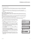
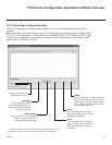
1. Install (if necessary) and launch the FTG Device
Configuration Application (v5.0.0 or higher) on the
PC that will be used to configure the EBL.
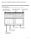
2. Build an FTG Channel Map using the FTG Channel
Map Editor in the FTG Channel Map Configuration
Utility (or, if applicable, open an existing FTG
Configuration [.rml] file).
Note: Up to 141 logical channels can be defined in the
FTG Channel Map.
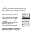
3. Connect the PC to the TV-LINK CFG jack on the TV’s
rear connections panel using a USB-to-TTL serial
cable (TTL-232R-5V-AJ). If necessary, install the
device driver on the PC.
4. Turn ON the TV.
Note: If Installer Menu item 118 POWER SAVINGS is
set to 3 (default), the TV must be ON in order for steps
5 and 6 below to be successful.
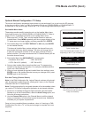
5. “Write” the FTG Channel Map to the EBL (switches the
EBL from Pass-through Mode to FTG Mode).
Note: After a “Write” of new data, the TV will briefly
display a green text banner that shows the EBL firm-
ware version and release date.
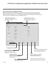
6. “Read” the current FTG Installer Menu settings from
the EBL using the FTG Installer Menu Configuration
Utility. If necessary to make changes to Installer Menu
items, “Write” them back to the EBL in FTG Mode.
7. Save the FTG Channel Map and FTG Installer Menu
settings to an FTG Configuration (.rml) file for future
use.
8. Tune the TV to a Logical Channel in the FTG Channel
Map.
Rear Jack Panel