


48
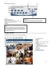
Appendix 3: Pin Configurations
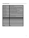
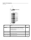
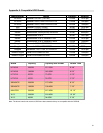
25 Pin Com Port
EXTERNAL ALAM NO
EXTERNAL ALARM COM
PIN OFF
ALARM INPUT 9
ALARM INPUT 10
ALARM INPUT 11
ALARM INPUT 12
ALARM INPUT 13
ALARM INPUT 14
ALARM INPUT 15
ALARM INPUT 16
ALARM INPUT 1
ALARM INPUT 2
ALARM INPUT 3
ALARM INPUT 4
ALARM INPUT 5
ALARM INPUT 6
ALARM INPUT 7
ALARM INPUT 8
PIN OFF
GND
DVR
PIN13
Under normal operations COM disconnects with NO. When the Alarm is
triggered, COM connects with NO.
EXTERNAL ALARM NO
PIN 25
Under normal operations COM disconnects with NO. When the Alarm is
triggered, COM connects with NO.
EXTERNAL ALARM COM
PIN 10,14
----
PIN OFF
PIN 2-9;
PIN 15-22
To connect wire from ALARM INPUT (PIN 2 -- 9; PIN 15-22) to GND
(PIN 1) connector, DVR will start recording and buzzer will sound.
¾ When Menu / Camera / Alarm is set to “Low”: the unit starts to
record and the buzzer sounds.
¾ When Menu / Camera / Alarm is set up to “High”: the unit starts to
record and the buzzer sounds.
ALARM INPUT
PIN 1
GROUND
GND