CH3 CH4
RF OUT
ANT.IN
AUDIO
VIDEO
IN OUT
IN OUT
R
L
75Ω
ANT /
CABLE
OUT
IN
8 Hookups with a Cable Box/Direct Broadcast System
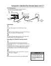
Connections
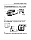
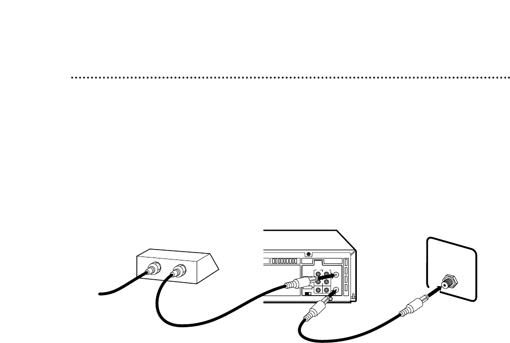
1
Connect a Cable signal to the IN jack on the Cable Box/DBS.
2
Use an RF coaxial cable (supplied) to connect the OUT jack on
the Cable Box/DBS to the ANT(enna) IN jack on the VCR.
3
Use a second RF coaxial cable to connect the RF OUT jack on the
VCR to the TV’s ANTENNA IN jack.
Recording/Viewing Any Channel
1
With the VCR on and in VCR position (the VCR light will appear
on the display panel), use the CH(annel) 8/9 button to set the
VCR to the Cable Box/DBS output channel (channel 03 or 04).
2
Set the TV to the same channel to which you set the VCR. Set the
CH3/CH4 switch on the VCR to the same channel.
3
Select the channel you want to view/record at the Cable
Box/DBS.
1
2
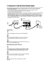
There are two ways to connect your Cable Box/DBS to the VCR. With this connection:
• You may view any channel.
• You must select channels at the Cable Box/DBS. Channels cannot be changed at the VCR.
• You may not view a channel other than the one you are recording.
• You may not set up channels at the VCR.
• You can only program a timer recording for one channel at a time. Set the TV and the VCR to the Cable
Box/DBS output channel (channel 03 or 04); set the CH3/CH4 switch to the same channel. Set your
Cable Box/DBS to the channel you want to record. When you enter the channel you want to record in a
timer recording, select channel 03 or 04 (the Cable Box/DBS output channel). (This is step 3 on page
36.) Leave the Cable Box/DBS on for a timer recording. (The VRA651 is illustrated here. The VRA451
has single AUDIO IN/OUT Jacks.)
3
Cable signal
RF coaxial cable
RF coaxial
cable
Cable Box/DBS
VCR
TV’s
ANTENNA
IN jack


