


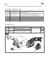
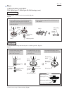
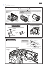
Circuit diagram
Color index of lead wires' sheath
Black
Red
White
Controller
Fig.D-1
DC motor
Switch
Terminal
Line filter
Line filter is not used
for some countries.
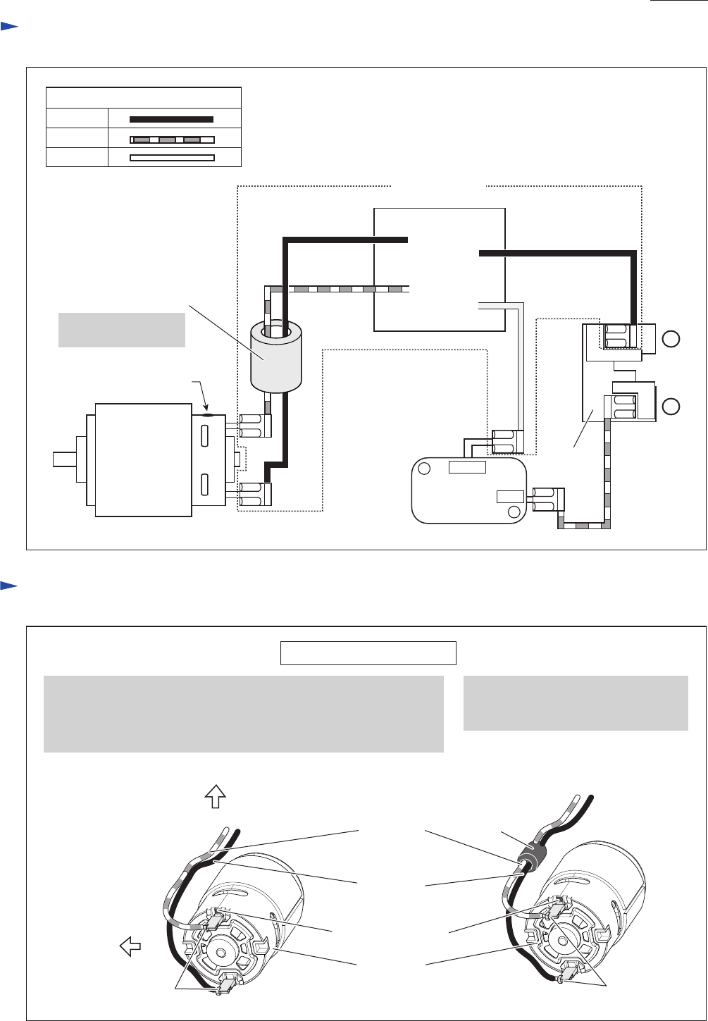
Fig.D-2
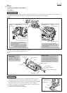
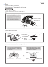
1. Connect the receptacle of Lead wire (red) to the Terminal with
red dot marking.
2. Connect the receptacle of Lead wire (black) to the other Terminal.
Note: Face each Lead wire to the direction drawn below.
Red dot marking
Receptacles
of Lead wire
Receptacles
of Lead wire
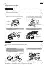
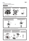
3. Pass Lead wire (red) and Lead wire
(black) through Line filter if Line
filter is used.
Line filter
DC motor
Left side
Top side
Wiring to DC Motor
Lead wire
(black)
Lead wire
(red)
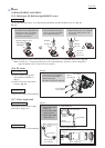
Wiring diagram
P 9/ 10
+
-
Controller unit
COM
NO
red dot marking