


4
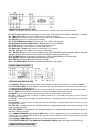
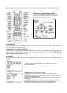
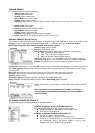
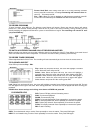
CONNECTORS AND DEFINITIONS
Please do not connect the power to the receiver until all other connections have been made and checked.
R1: AC IN (Power Cord) Connect this lead to the mains outlet (100-240 Volts AC, 50/60 Hz, 0.2Amps / 0.15Amps)
R2: LNB IN (IF Input) Connect the IF cable from your LNB to this connector.
R3: LOOP OUT If you have a second satellite receiver, connect the receivers LNB input to this connector.
R4: ANT IN Connect your TV antenna to this connector.
R5: TV OUT (Modulator Output) Connect your TV or VCR to this connector.
R6: Modulator channel output switch. Select channel of your preference.
R7: VIDEO Composite video output for connecting to an AV monitor etc.
R8: 0/12V Switched + 12V DC output for use with LNB switches.
R9: AUDIO LEFT / RIGHT Audio outputs for connecting to a Hi-Fi system.
R10: SP / DIF Digital audio output for connecting to a HiFi system
R11: RS-232 Connect your PC to this connector using a NULL MODEM (female to female) cable for software
upgrade. Connect STB for channel data transfer from another receiver of same model.
R12: S- VIDEO Additional video output for connecting to a VCR or CAMCORDER with S-VIDEO capability
R13: PULSE Connection for Mechanical Polarizer (Pulse output)
R14: GND Connection for Mechanical Polarizer (Ground)
R15: +5V 300mA MAX Connection for Mechanical Polarizer (+5V output)
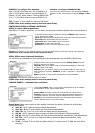
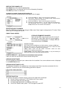
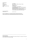
FRONT PANEL CONNECTORS
CONTROLS AND DEFINITIONS
F1: STANDBY / ON After connecting the power, press this button to switch ON the receiver or to switch to STANDBY
F2: DIGIT LED DISPLAY This will display the channel number or certain programming functions when using the menus.
In standby mode it will display the time.
F3: REMOTE CONTROL SENSOR Location of the infrared receiver. Do not obstruct this when using the remote control.
F4: TV / RADIO Press this button to change from TV channels to RADIO channels and vise versa.
F5: MENU Press this button to enter the programming menus. To exit the menus, press it again.
F6: OK In viewing mode press this button to display channel list. In menu mode this button is used to enter the
programming parameters.
F7: CH UP In viewing mode it will step up channels sequentially. In programming mode it will move the cursor upwards
in the menu.
F8: CH DOWN In viewing mode it will step down channels sequentially. In programming mode it will move the cursor
downwards in the menu.
F9: VOL UP In viewing mode it will increase the sound. In programming mode it will move the cursor to the
right or change a function.
F10: VOL DOWN In viewing mode it will decrease the sound. In programming mode it will move the cursor to
the left or change a function.
F11: COMMON INTERFACE (CI) SLOTS A AND B Your receiver is equipped with two slots (behind the front flap)
accepting Type 1 and Type 2 PCMCIA modules. Open flap from top catch (F14) and Insert CI module together with smart
card into either of these slots.
F12: CI SLOTS A AND B EJECT When you want to remove a cam press the eject button.
F13: IRDETO CARD SLOT (For Models with embedded Irdeto) Insert your smart card into this slot.
FRONT
PANEL CONTROLS
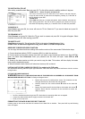
REMOTE
CONTROL FUNCTIONS