3 - 5
MELSEC-A
3 SPECIFICATION
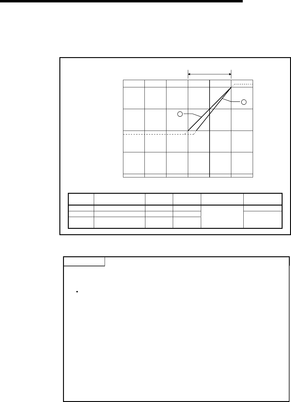
3.3.2 Current input characteristics
The current input characteristic graph is shown below.
2
1
4095
4000
2000
-2000
-4000
0
4
-30 -20 -10 0 10 20 30
Analog input current (mA)
Analog input
parcitcal value
-96
Digital output value
Number
Analog Input Range
Setting
Offset
Value
Gain
Value
Digital Output
Value*
Maximum
Resolution
1) 0 to 20mA 0mA 20mA 5µA
2) 4 to 20mA 4mA 20mA
—
User range setting 3
(0 to 20mA)
0mA 20mA
0 to 4000
4µA
Fig. 3.2 Current Input Characteristic
POINT
(1) Do not input more than ±30mA. A breakdown may result due to heat increase.
(2) If the analog input provided corresponds to the digital output value* beyond its
range, the digital output value is fixed to the maximum or minimum.
For 0 to 4000, the digital output value is within the range -96 to 4095.
(3) Within the analog input and digital output scopes of each input range, the
maximum resolution and accuracy are within the performance specification
range. Outside those scopes, however, they may not fall within the performance
specification range. (Avoid using the dotted line part in Fig. 3.2.)
(4) Set the offset and gain values of the user range setting within the range
satisfying the following conditions.
(a) Setting range when user range setting 3 is selected: 0 to 20mA
(b) (Gain value) > (Offset value)
If you attempt to make setting outside the setting range of (a), the "RUN" LED
flickers at 0.5s intervals.
Set the values within the setting range.
If you attempt to make setting outside the setting range of (b), the "RUN" LED
flickers at 0.5s intervals.
Make setting again.


