5 - 7
MELSEC-A
5 PROGRAMMING
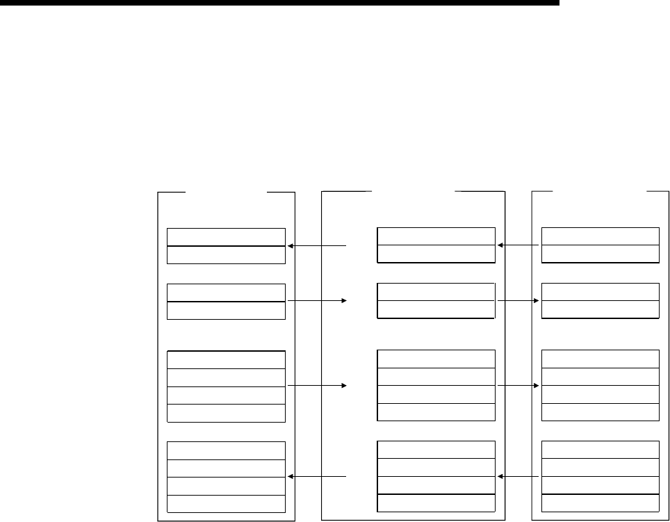
5.2.2 Program examples for use of the ACPU/QCPU (A mode) (dedicated instructions)
The program examples in this section are created under the following conditions.
A sequence program is used to set the network and automatic refresh parameters.
[Relationships between PLC CPU, master module and AJ65SBT-64AD]
PLC CPU
Device X
Device Y
Device D
X100 to X10F
X110 to X11F
Y100 to Y10F
Y110 to Y11F
D200
D201
D202
D203
Device D
D456
D457
D458
D459
Master module
Address
Remote input (RX)
RX00 to RX0F
RX10 to RX1F
E0
H
E1
H
Remote output (RY)
RY00 to RY0F
RY10 to RY1F
160
H
161
H
Remote register (RWw)
RWw0
RWw1
RWw2
RWw3
1E0
H
1E1
H
1E2
H
1E3
H
Remote register (RWr)
RWr0
RWr1
RWr2
RWr3
2E0
H
2E1
H
2E2
H
2E3
H
AJ65SBT-64AD
(Station number 1)
Remote input (RX)
RX00 to RX0F
RX10 to RX1F
Remote output (RY)
RY00 to RY0F
RY10 to RY1F
Remote register (RWw)
RWw (A/D conversion
enable/prohibit specification)
RWw2 (Moving average processing
count setting)
RWw3 (Reserved)
RWw1 (Input range setting)
Remote register (RWr)
RWr (CH.1 digital output value)
RWr2 (CH.3 digital output value)
RWr3 (CH.4 digital output value)
RWr1 (CH.2 digital output value)
[Initial settings]
A/D conversion enabled channels.................Channels 1, 2
Moving average processing channel.............Channel 2 count setting = 16 times
Input range setting .........................................Channel 1: 0 to 5V
Channel 2: User range setting 1


