


Part Name 3
3-1
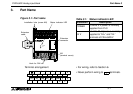
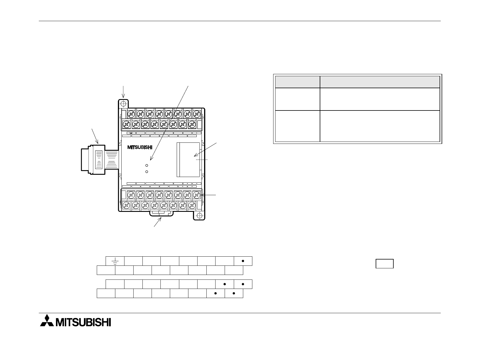
3. Part Name
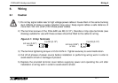
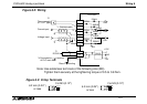
• For wiring, refer to Section 6.
• Never perform wiring to terminals.
Table 3.1: Status indicator LED
Indication Description
POWER
Lit while 5 V power is normally
supplied from PLC.
24 V
Lit while 24 V power is normally
supplied to “24+” and “24-”
terminals of FX
2N
-8AD.V
V1+ I1+
COM1
V3+ I3+
24+ 24- V2+ I2+ V4+ I4+
COM4
COM3
COM2
I6+
COM5
V7+ I7+
V6+
V5+ I5+
V8+ I8+
COM8
COM7
COM6
V8+
COM7
COM6
I6+
I7+
V6+
V5+
COM4
I1+V1+
V7+
V4+I2+V2+
24V
POWER
24-24+
I5+
COM8
COM5
COM1 COM3
I3+V3+
I4+
I8+
COM2
FX
2N
-8AD
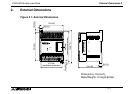
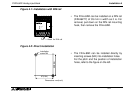
Installation hole (screw M4)
Status indicator LED
M3
(terminal screw)
Hook for DIN rail
Extension
cable
Extension
connector
Terminal arrangement
Figure 3.1: Part name
•
FX2N-8AD Analog input block