


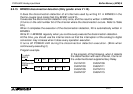
FX2N-8AD Analog input block Buffer Memory (BFM) 8
8-31
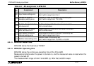
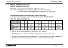
8.2.18 BFM #71 to BFM #78: Lower limit, error set value
BFM #81 to BFM #88: Upper limit, error set value
When using the upper/lower limit value detection function (BFM #22 b1), write the lower limit
value of each channel to BFM #71 to BFM #79 and the upper limit value of each channel to
BFM #81 to BFM #88.
When using the data addition function (BFM #22 b0) together, write the value added by the
addition data (BFM #61 to BFM #68) to BFM #71 to BFM #78 and BFM #81 to BFM #88.
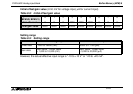
Setting range
The setting range varies depending on the setting of the input mode (BFM #0, BFM #1).
The table below shows the setting range in each input mode. Write the set value in a digital
value.
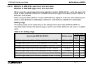
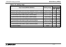
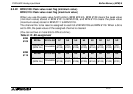
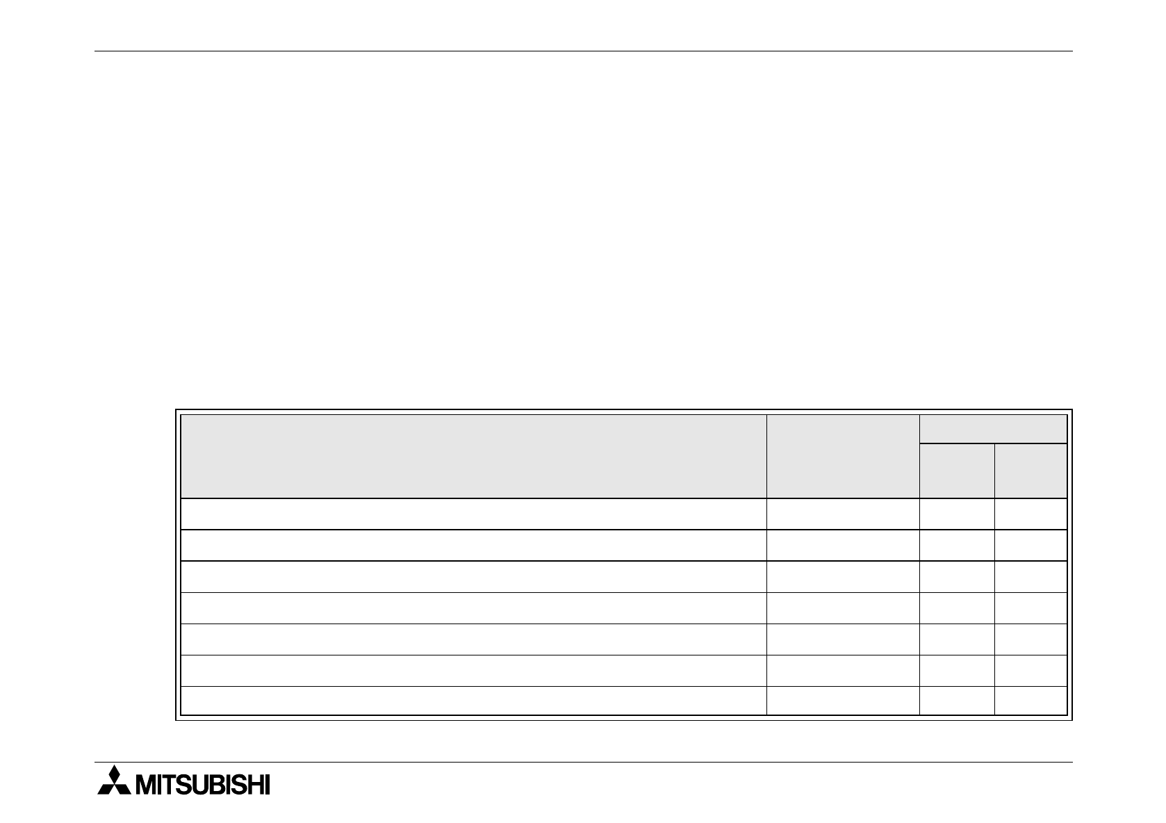
Table 8.10: Setting range
Input mode (BFM #0, BFM #1) Setting range
Initial value
Lower
limit
Upper
limit
0: Voltage input mode (-10 to +10 V), resolution 10 V x 1/16,000 -16384 to 16383 -16384 16383
1: Voltage input mode (-10 to +10 V), resolution 10 V x 1/4,000 -4096 to 4095 -4096 4095
2: Voltage input mode, analog value direct display (-10,000 to +10,000)
-10200 to 10200 -10200 10200
3: Current input mode (4 to 20 mA), resolution 20 mA x 1/8,000 -1 to 8191 -1 8191
4: Current input mode (4 to 20 mA), resolution 20 mA x 1/4,000 -1 to 4095 -1 4095
5: Current input mode, analog value direct display (4,000 to 20,000) 3999 to 20400 3999 20400
6: Current input mode (-20 to +20 mA), resolution 20 mA x 1/8,000 -8192 to 8191 -8192 8191