14
Warning:
Don’t display the same stationary images on the screen for more than 15% of your total TV viewing in
one week. Examples of stationary images are letterbox top/bottom bars from DVD disc or other video sources, side
bars when showing standard TV pictures on widescreen TV’s, stock market reports, video game patterns, station logos,
web sites or stationary computer images. Such patterns can unevenly age the picture tubes causing permanent
damage to the TV. Please see page 74 for a detailed explanation.
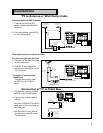
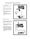
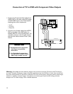
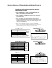
Connection of TV to DVD with Component Video Outputs
1. Connect the Component Video cables from
VIDEO OUT on the back of the DVD player
to DVD VIDEO input on the TV back panel,
matching the correct components:
• Y to Y,
• Cr to Cr,
• Cb to Cb.
2. Connect a set of audio cables from AUDIO
OUT on the back of the DVD player to
AUDIO, INPUT-3 on the TV back panel. The
red cable connects to the R (right) channel
and the white cable connects to the L (left)
channel.
R
L
ANALOG
VIDEO OUT
Y
Cb
Cr
1
2
AUDIO OUT
DVD back panel
TV back panel
ANT-B
LOOP
OUT
ANT-A
S-VIDEO V L
R
(MONO)
YCrCb
VIDEO AUDIO
INPUT-1
INPUT-2
INPUT-3
HDTV VIDEO
Y
Pr
H V
HDTV CONTROL
HDTV AUDIO
LR
(MONO)
VL
R
(MONO)
IR
HOME
THEATER
ACTIVE A/V
NETWORK
MONITOR
OUTPUT
VIDEO AUDIO
DVD VIDEO
HIGH-DEFINITION INTERFACE
Pb
IMPORTANT IMPORTANT
IMPORTANT IMPORTANT
IMPORTANT
IMPORTANT IMPORTANT
IMPORTANT IMPORTANT
IMPORTANT
1. See Appendix 4 for component
video signal compatibility
information.
2. For Digital Audio connections,
see the Owner's Guides of your
DVD Player and AV receiver.


