


MODELS: VS-45609 / VS-50609 / VS-55609 / VS-60609 / VS-60719 / VS-70709
Page 37
MODELS: VS-45609 / VS-50609 / VS-55609 / VS-60609 / VS-60719 / VS-70709
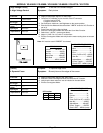
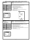
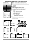
Purpose:
Measuring
Instrument
Test Point
Measuring
Range
Input Signal
Ext. Trigger
Input Terminal
Symptom:
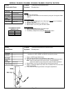
[Convergence Circuit]
-----
-----
------
-----
Monoscope
RF or Video
To set the Convergence circuit geometry adjustments.
Raster distortion at the top, bottom or sides of the picture.
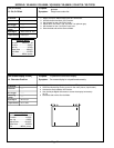
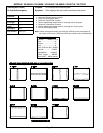
Note:
Vertical Height and Vertical Linearity Adjustments must be performed before
this adjustment.
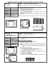
Coarse Adjustment
1. Supply a Monoscope signal to the RF or Video Input.
2. Select the Monoscope as the signal source (Input button).
3. Activate the Convergence Mode, Coarse Green Function
4. Adjust Item “5 HWID” so the sum of the horizontal markers is 7.6.
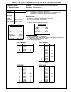
5. Set the data of the following items for straight crosshatch lines.
• “3 SKEW” ... Skew
• “4 TILT” ... Tilt
• “6 HLIN” ... Horizontal Linearity
• “7 SPCC” ... Side Pin Cushion Correction
• “8 HKEY” ... Horizontal Keystone
• “9 TBPC” ... Top/Bottom Pin Cushion
• “10 VKEY” ... Vertical Keystone
• “11 VWID” ... Height
• “12 VLIN” ... Vertical Linearity.
Note: If the raster centering changes during the adjustments, correct the
centering using Items “1 HSTA” and “2 VSTA”.
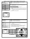
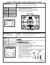
Fine Adjustment
6. Activate the Fine Green Convergence Mode. (Press 4)
7. Use the Cursor to adjust for straight crosshatch lines.
8. Exit the Convergence Mode.
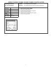
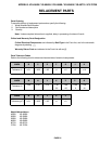
18. Geometry Adjustment
CONVERGENCE MODE
Activate ……..MENU-0-1-5-9
Misc. ……………….……"6"
Coarse………………..…."5"
Fine ……………………..."4"
Color (R,G B or DF)...AUDIO
Item No………….…..VIDEO
Adjust/Move……….ADJUST
Cursor Toggle….…..ENTER
Save & Exit…..MENU (twice)