


24
25
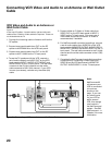
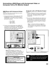
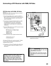
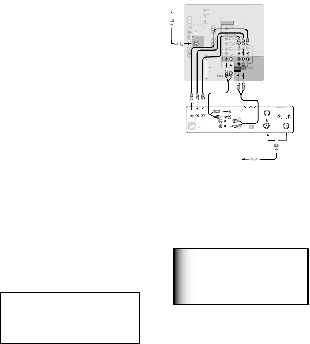
Connecting a DTV Receiver with RGB, HV Video
DTV Receiver with RGB, HV Video
Figure 13
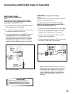
A coaxial splitter, RGB, HV and audio cables are required.
These are not included with the TV.
1. Connect the outside antenna, cable or satellite to
ANT or SATELLITE IN on the DTV receiver (see your
DTV receiver owner’s guide for instructions and
cable compatibility).
2. Connect the incoming terrestrial antenna or cable
(not satellite) to ANT-1 on the TV back panel
(a coaxial splitter, available at most electronic
supply stores, may be required to complete this
installation).
3. Connect RGB cables from the DTV receiver to Input-
DTV on the TV back panel.
DTV Receiver to TV Back Panel
• G (green) to Y/G
• R (red) to Pr/R
• B (blue) to Pb/B
4. Connect the H & V sync signals as shown below:
• H (horizontal sync) to H
• V (vertical sync) to V
All 5 cables (G,R,B,H and V) must be connected. 3 cables
or Sync on green connections are incomplete or not
compatible and will not work.
5. Connect the L (left) and R (right) audio cables from
the DTV Receiver to Input-DTV AUDIO on the TV
back panel.
See Appendix B for RGB, HV video signal
compatibility information.
For digital audio connections, see your
DTV Receiver and A/V receiver Owner’s
Guides.
IMPORTANT
IREMITTER
NetCommand
R
INPUT-1
AUDIO2
AUDIO/VIDEO1
AUDIO
L(MONO)R
INPUT-2
COMPONENT-1
YPbPr(480i/480p/720p/1080i)
Y/G
Pb/BPr/R
COMPONENT-2
YPbPr(480i/480p/720p/1080i)
INPUT-DTV
YPbPr/RGBHV
(480i/480p/720p/1080i)
DTV/
CABLE/
VHF/
UHF
ANT-2
AUX
ANT-1
MAIN
DIGITAL
AUDIO
PC
VGA/SVGA/XGA/
720p
60Hz
PC-
AUDIO
PC-
INPUT
M-LINK
CONTROL/
RS-232C
HDMI
M-LINK
IEEE1394
INPUT/OUTPUT
VIDEO S-VIDEO
MONITOR
OUTPUT
L
R
V H
CARD
TOP
CableCARDSLOT
TM
DTV Receiver
(with RGB connections)
G
R
B
S
-
V
I
D
E
O
V
C
R
C
O
N
T
R
O
L
P
H
O
N
E
J
A
C
K
R
F
R
E
M
O
T
E
O
U
T
T
O
T
V
C
H
3
C
H
4
C
A
U
T
I
O
N
R
I
S
K
O
F
E
L
E
C
T
R
I
C
A
L S
H
O
C
K
D
O
N
O
T
O
P
E
N
D
I
G
I
T
A
L
A
U
D
I
O
O
U
T
White
Red
Incoming
Antenna
or Cable
SATELLITE IN
IN FROM ANT
or
to antenna,
cable or satellite
A
U
D
I
O
L
R
H
V
1.
1.
4.
4.
5.
4.
5.
3.
3.
2.
2.
TV back panel
DVI
AnalogAudio
L
R
AUDIO
L(MONO)R
White
Red
w
h
i
t
e
R
e
d
Figure 13. Connecting an External DTV Receiver with
RGB Video Connections
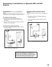
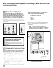
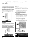
It may be necessary to obtain a VGA to RGB,
HV adaptor cable. These are available at
most computer stores and many electronic
stores. Some of the adaptor cables have
RCA type connector ends, others have BNC
type ends and will require adaptors as shown
on page 24.