


26
27
Connecting M-Link Control RS-232C Connection, or a HDMI
or DVI Device
TVbackpanel(sectiondetail)
IREMITTER
NetCommand
R
DTV/
CABLE/
VHF/
UHF
ANT-2
AUX
ANT-1
MAIN
DIGITAL
AUDIO
PC
VGA/SVGA/XGA/
720p
60Hz
PC-
AUDIO
PC-
INPUT
M-LINK
CONTROL/
RS-232C
HDMI
M-LINK
IEEE1394
INPUT/OUTPUT
L
R
CARD
TOP
CableCARDSLOT
TM
Computer with Monitor Output
L
R
DVI
AnalogAudio
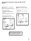
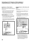
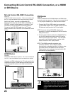
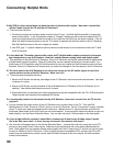
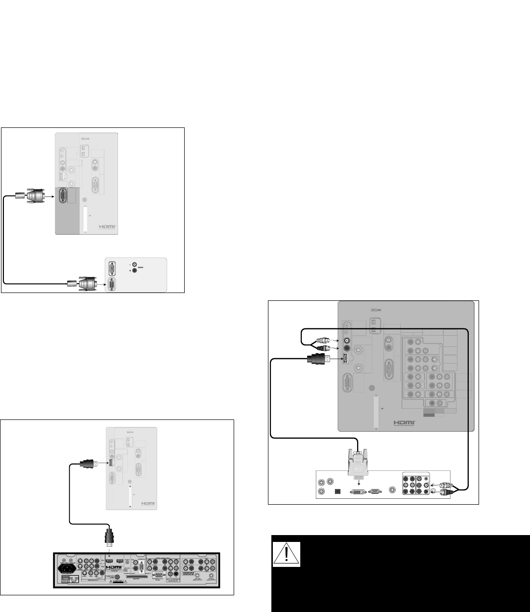
M-Link Control RS-232C Connection
Figure 14
A 9 pin RS-232C cable is required. This is not included with
the TV. It may be available at your local electronics retailer
As M-Link Control, connect to a Mitsubishi HD
Receiver/Controller, like the HD-5000 or HD-6000. As
RS-232C, connect to other external controllers. See
mitsubish-tv.com for RS-232C command protocol.
Connect a 9 pin RS-232C cable from the TV back
panel to the M-Link or RS-232C on the external control
device.
Figure 14. Connecting M-Link Control
HD-6000 Receiver
TV back panel (section detail)
IREMITTER
NetCommand
R
DTV/
CABLE/
VHF/
UHF
ANT-2
AUX
ANT-1
MAIN
DIGITAL
AUDIO
PC
VGA/SVGA/XGA/
720p
60Hz
PC-
AUDIO
PC-
INPUT
M-LINK
CONTROL/
RS-232C
HDMI
M-LINK
IEEE1394
INPUT/OUTPUT
L
R
CARD
TOP
CableCARDSLOT
TM
L
R
DVI
AnalogAudio
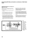
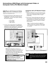
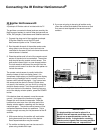
Figure 15. Connecting HDMI Device
HDMI Device
Figure 15
An HDMI to HDMI cable is required. This is not included with
the TV. It may be available at your local electronics retailer
Connect an HDMI cable from the TV back panel to the
HDMI device output. HDMI devices provide video and
audio through this cable, so no other connection is
required.
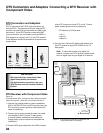
CAUTION: To ensure continued FCC
compliance, the user must use a shielded
video interface cable with bonded ferrite
cores at both ends when using the PC
input.
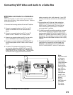
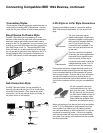
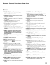
DVI Device
Figure 16
A DVI-to-HDMI cable or DVI/HDMI adaptor and HDMI cable
and audio cables are required. These are not included with the
TV. They may be available at your local electronics retailer.
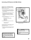
1. Connect the DVI-to-HDMI cable (recommended)
(or DVI/HDMI adaptor with an HDMI cable) from the
DVI device’s back panel to the TV back panel.
NOTE: If you are using a DVI/HDMI adaptor, it is
important to connect the adaptor to the DVI side for
best performance.
2. Connect a set of audio cables from AUDIO OUT on
the the DVI device back panel to the DVI Analog
Audio input on the TV back panel. The red cable
connects to the R (right) channel, and the white
cable connects to the L (left) channel.
NOTE: The HDMI connection supports copy
protection (HDCP). Some devices require
connecting to an analog input first, in order to view
on-screen menus and select DVI as the ouput.
Please review your equipment instructions for DVI
connectivity and compatibility.
DVI DEVICE
DVI-TO-HDMI CABLE
2.
2.
1.
IREMITTER
NetCommand
R
DVI
AnalogAudio
INPUT-1
AUDIO2
AUDIO/VIDEO1
AUDIO
L(MONO)R
INPUT-2
COMPONENT-1
YPbPr(480i/480p/720p/1080i)
Y/G
Pb/BPr/R
COMPONENT-2
YPbPr(480i/480p/720p/1080i)
INPUT-DTV
YPbPr/RGBHV
(480i/480p/720p/1080i)
DTV/
CABLE/
VHF/
UHF
ANT-2
ANT-1
DIGITAL
AUDIO
PC
VGA/SVGA/XGA/
720p
60Hz
PC-
AUDIO
PC-
INPUT
M-LINK
CONTROL/
RS-232C
HDMI
M-LINK
IEEE1394
INPUT/OUTPUT
VIDEO S-VIDEO
MONITOR
OUTPUT
L
R
V H
CARD
TOP
CableCARDSLOT
TM
MAIN
AUX
1.
L
R
DVI
AnalogAudio
L
R
DVI
AnalogAudio
HDMI
M-LINK
Figure 16. Connecting a DVI Device