3-5
Standard Standby Supplies
Two Standby supplies are generated directly from
T9A20, 12VS and 6VS. Both of these supplies are
directed to the DM module, and are denoted as 12V-
DM and 6V-DM.
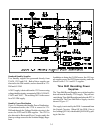
A 30VS supply is derived from the 12VS source using
voltage doubler circuitry, comprised of D9A31, D9A32,
C9A32 and C9A27. The resulting 30VS is the source
for a 28V-DM supply.
Standby Power Distribution
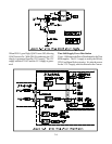
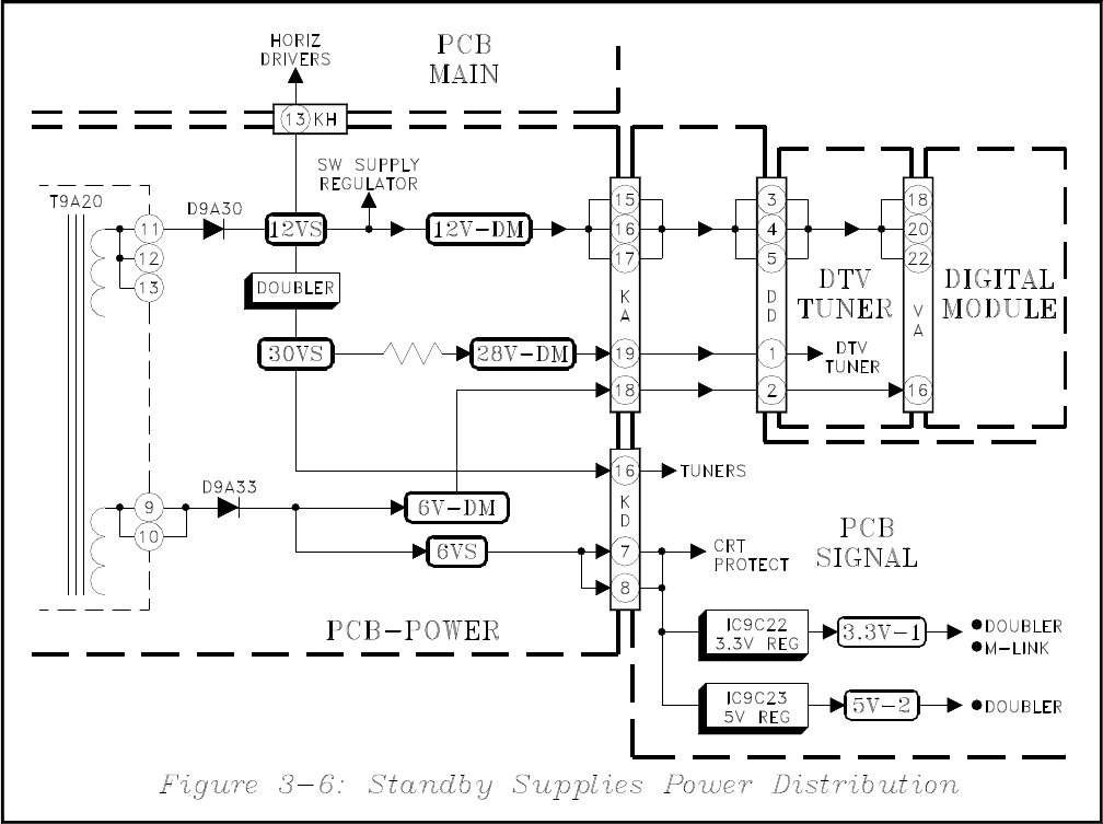
Figure 3-6 illustrates the Standby Power Distribution.
As mentioned earlier, the 12VS is source for 12V-
DM,and through the Voltage Doubler circuitry is the
source for 30VS and 28-DM supplies. The 12VS is
also directed to Horizontal Drive Circuitry and is the
Start-up voltage source for the Switched Supply Regu-
lator.
In addition to being the 6V-DM source, the 6VS sup-
ply supplies power for CRT Protect circuitry, and is the
source for the 3.3V-1 and 5V-2 supplies.
Time Shift Recording Power
Supplies.
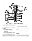
The Time Shift Record Supplies are switched supplies
derived from the Standby 12VS supply. They are acti-
vated during Time Shift Recording and when the PTV is
switched On. The Time Shift Power Supply circuit is
shown if Figure 3-7.
The supply is activated by the PON-1 command from
the Control Circuitry. When Off, the PON-1 line is
low, holding Q921 On, which holds Q9A20 Off by pull-
ing its Gate low.


