6-6
Horizontal Deflection DC Supply Circuitry
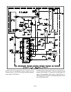
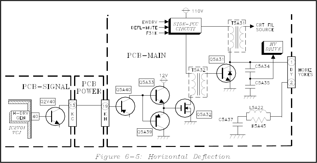
The DC supplies for Q5A32 and Q5A31 are derived
from Horizontal Deflection DC Supply circuitry. The
31K line from the Control µPC controls the DC volt-
age for Q5A31. Q5A31 supply voltage is approxi-
mately 10 volts higher for the 33.75 kHz scan for-
mat (1080i), than that for the 31.5 kHz scan (480p),
The H-Deflection DC Supply circuitry is also used
to:
• Add side pincushion correction, controlled
by the EWDRV signal from the VCJ.
• Reduce the Deflection DC supply during
scanning frequency changes.
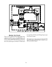
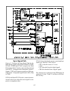
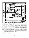
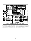
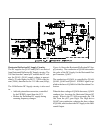
Figure 6-6 shows the Horizontal Deflection DC Sup-
ply circuitry. The conduction of Q5A01 determines
the value of the DC Supply for the Horizontal Out-
put Transistor, Q5A31.
The conduction of Q5A01 is controlled by Q5A06,
Q5A05, Q5A03 and Q5A02. EWDRV signal is ap-
plied to the base of Q5A06 for Side Pincushion Cor-
rection.
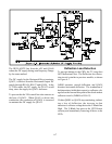
When the base voltage of Q5A06 decreases, Q5A01
conducts less, lowering the Horizontal Output DC
supply. When is the 31.5 kHz scan mode, the 31K
line from the µPC goes High. The High drives
Q5A07 into conduction, reducing the base voltage
of Q5A06, which reduces the DC supply to the Hori-
zontal Output.


