29
Recording
Chapter 2 Recording and Playback
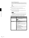
When the REMOTE indicator is lit, selection of the time data type is carried
out at the editing control unit.
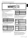
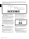
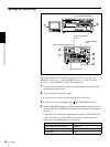
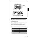
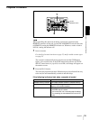
5 Select the formats of video and audio input signal to be recorded.
Use the INPUT SELECT buttons in the video/audio input setting section to
select the desired signal formats. Each selection is shown by a lit indicator
in the INPUT signal display section.
a) The indicators without the corresponding optional boards (DSBK-1501/1505) installed in the
unit do not light.
a) The indicators without the corresponding optional boards (DSBK-1501/1505) installed in the
unit do not light.
Caution
Once you have started recording, you cannot change the input signal
selection.
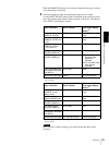
Video input signal
(input connector)
Corresponding INPUT
SELECT button
Lit indicator in the
INPUT signal display
section
a)
Composite signal
(VIDEO IN: Y/CPST)
VIDEO COMPOSITE in VIDEO
group
Separated Y/C signal
(VIDEO IN: Y/CPST and
R−Y/C)
VIDEO S VIDEO in VIDEO
group
Component signal
(VIDEO IN: Y/CPST,
R−Y/C, and B−Y)
VIDEO Y−R,B in VIDEO group
SDI signal
(SDI/SDTI (QSDI) IN)
VIDEO SDI in VIDEO group
SDTI (QSDI) signal
(SDI/SDTI (QSDI) IN)
SDTI/i.LINK SDTI: both SDTI video
and audio input
signals are
recorded.
V:SDTI: only SDTI video
input signal is
recorded.
i.LINK-compatible digital
video signal in DV format
(i.DV IN/OUT)
SDTI/i.LINK i.LINK
Internal test video signal VIDEO SG in VIDEO group
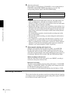
Audio input signal
(input connector)
Corresponding INPUT
SELECT button
Lit indicator in the
INPUT signal display
section
a)
Analog signal
(AUDIO IN 1/3 and
AUDIO IN 2/4)
CH1 1/2 and CH2 3/4 ANALOG in AUDIO
group
AES/EBU signal
(AUDIO (AES/EBU) IN)
CH1 1/2 and CH2 3/4 AES/EBU in AUDIO
group
SDI signal
(SDI/SDTI (QSDI) IN)
CH1 1/2 and CH2 3/4 SDI in AUDIO group
SDTI (QSDI) signal
(SDI/SDTI (QSDI) IN)
SDTI/i.LINK SDTI
i.LINK-compatible digital
audio signal in DV format
(i.DV IN/OUT)
SDTI/i.LINK i.LINK
Internal test audio signal CH1 1/2 and CH2 3/4 SG in AUDIO group


