


13
Parts and their functions
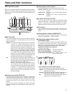
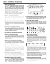
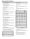
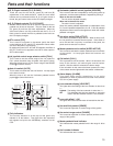
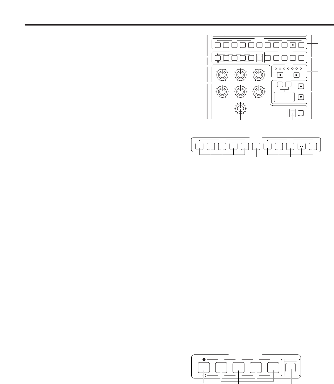
LCD display
This shows the adjustment items and adjustment values
when the control item selector switches ? have been
selected.
@
Adjustment rotary encoders
These enable the data of the adjustment items shown on the
LCD display @ to be changed.
A
FILTER
SCENE FILE MONITOR
GAIN
SHUTTER
ND
HEAD
CAP 100 25 6.3 1.6
1234 R
-6
ON VAR
FULL AUTO
-3 0 3 6 9 12
G B SEQ ENC
STORE
GAIN
G
CC
4.3 6.33.2 DFO
DTL
R B
BLACK
G
BR
B
D
C
E
F
G
H
L
J K
5678
B
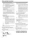
FILTER
ND
HEAD
CAP 100 25 6.3 1.6
CC
3.2 4.3 6.3 DFO
2
1 3
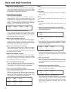
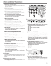
1ND filter switches [ND FILTER 1, 2, 3, 4, 5]
These are the ND filter selector switches. The filter setting
can be changed when the HEAD switch lamp is off.
ND1: Cap
ND2: Through (green light emitted)
ND3: 1/4
ND4: 1/16
ND5: 1/32
2HEAD switch [HEAD FILTER]
This is used to switch the control over the filter to the
camera head. Its lamp lights when filter control by the
camera head is enabled, and it goes off when filter control
by this panel or MSU is enabled.
The lamps of the HEAD switches on this panel and MSU
will light also when the LOCAL switch on the operation
panel at the back of the studio camera has been pressed
and its lamp is lighted.
3CC filter switches [CC FILTER A, B, C, D, E]
These are the CC filter selector switches. The filter setting
can be changed when the HEAD switch lamp is off.
CCA: 3200K (green light emitted)
CCB: 4300K
CCC: 6300K
CCD: Cross
CCE: DF0
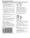
C
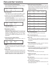
SCENE FILE
1234
STORE
5678
2
1
3
1Scene file switches [SCENE FILE 1 to 8]
These enable the camera settings for each scene or the
data in the adjustment data that can be transferred to
another camera to be saved in or called from eight files
that serve as scene files.
POWER (FAN): Fan power switch
This is used to set the power of the camera head’s fan to
ON, OFF, or AUTO.
SPEED (FAN): Fan speed
This is used to set the speed of the camera head’s fan.
2D-M: Component 2-dimensional low-pass filter
This is used to set whether to apply the 2-dimensional low-
pass filter to the SDTV component output.
2D-E: Composite 2-dimensional low-pass filter
This is used to set whether to apply the 2-dimensional low-
pass filter to the SDTV composite output.
COMB: Comb filter mode
This is used to set the comb filter mode.
AUTO SETUP MODE: Auto setup mode setting
This is used to select the auto setup mode setting.
MPED: Auto setup MPED convergence value
This is used to set the position where the master pedestal
is to be converged when auto setup has been started.
FSEL: File select
This is used to select the file attribute to be referenced
when auto setup has been started.
BRIGHT: Dot matrix display brightness setting
This is used to set the brightness of the dot matrix display.
CONT: LCD display contrast setting
This is used to set the LCD display contrast.
BUZZ: ROP buzzer setting
This is used to set the panel’s buzzer to ON or OFF.
CAMNO: Camera number setting
This is used to set the number of the camera to which this
unit is connected.
DTL (PAINT): DTL control mode
This is used to set the paint control DTL to SD or HD.
BLACK (PAINT): BLACK control mode
This is used to set the paint control BLACK to be used
with the flare, pedestal or gamma.
<CARD>: SD card read/write setting
This is used to write the camera’s data on the SD card or
read it from the card.