5
Parts and their functions
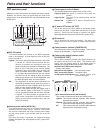
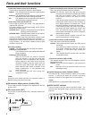
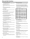
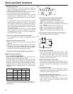
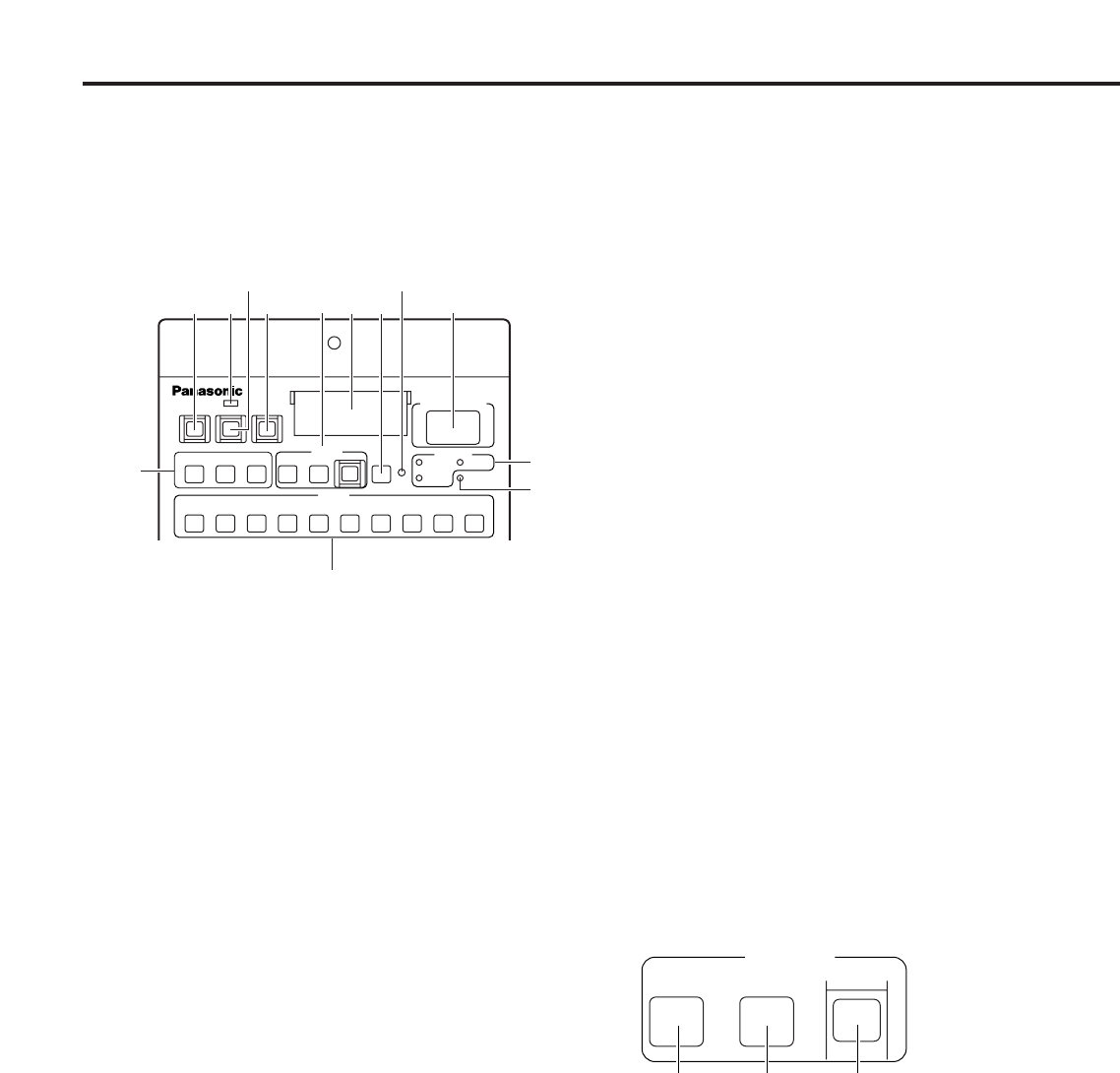
Camera number indicator [CAMERA NO.]
This indicates the camera number information. If the camera
number is not indicated, “–” appears instead.
6
Camera video output selector switch
[CLOSE/BAR/ TEST]
This is used to select the camera video signals which are to
be output from the CCU’s rear panel. The camera video
signal, color bar display signal or test display signal is
selected by pressing the BAR switch and/or TEST switch.
Both BAR and TEST switch lamps off:
Camera video output
BAR switch lamp lighted: Color bar signal output
TEST switch lamp lighted: Test signal output
CLOSE switch lamp lighted: Lens closed status with
camera video output
1Auto white balance switch [AUTO WHITE]
This is used to automatically adjust the white balance.
Lighted: This indicates that the automatic white balance
adjustment has started.
Flashing:This indicates that the automatic white balance
adjustment ended without being completed.
Off: This indicates that the automatic white balance
adjustment was completed correctly.
7
8
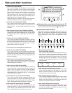
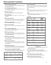
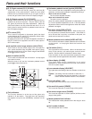
ROP ON switch
This switch enables the controls on the ROP’s operation
panel to be operated. Its lamp lights as soon as the CCU
power is turned on.
Lighted: The lamp of the switch lights when the CCU power
is turned on. When communication with the
camera is enabled, the settings at which the
panel's switches are selected are established. The
panel is set on the basis of the camera setting
information also immediately after the ROP ON
switch is pressed and its lamp is lighted. However,
if it is judged that communication with the camera
has been cut off, the setting at which the panel’s
switches are selected will not be established, and
the ROP ON switch lamp will remain lighted.
Off: The lamp turns off and the panel’s operations are
cancelled (protected status) when this switch is
pressed (while its lamp is lighted) while the CCU’s
power and the camera’s power is ON.
However, even when the ROP ON switch lamp is
off, the panel’s GAIN, FLARE and DTL controls
can be operated provided that the active indicator
is lighted. It is also possible to operate the iris
close switch irrespective of the ROP ON switch
setting provided that communication with the
camera is enabled.
1
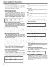
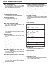
Camera power switch [HEAD ON]
This switch enables the panel to be used to operate the
camera’s power by remote control. However, this function
will not work unless both the CCU’s camera power switch
and the power switch on the camera itself are at the ON
position.
Each time the switch is pressed, the status alternates
between ON (power ON: LED lighted) and OFF (power OFF:
LED off).
2
Camera power switch indicator
This indicates whether the camera power is ON or OFF.
Lights up green:The panel is communicating with the
camera.
Lights up red: The panel is not communicating with the
camera.
Flashes red: POWER OFF status established by
software.
3
VF power OFF switch [VF OFF]
This is the camera VF power switch for exercising remote
control from the panel. It lights when the switch is in the ON
position. Each time the switch is pressed, the status
alternates between ON (power ON) and OFF (power OFF).
4
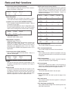
SD card slot
This is where the SD cards are inserted. The data of the
camera and CCU can be saved on these cards and then
called.
5
ROP ON
CLOSE
5600K OFF
FLARE
GAMMA ON
BLK
OFF
GAMMA
OFF
KNEE
CLIP OFF
WHITE
ON
MATRIX
OFF
HD. DTL
OFF
SD. DTL
BAR TEST
CHARACTER
RST
OPT FAN
60Hz
CABLE
WHITE
SET UP
BLACK
HEAD ON VFPW
SD CARD
CAMERA NO.
ALARM
AUTO
MODE
1
2
34 859
:
6
7
;
<
=
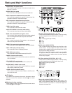
ROP operation panel
When any of the panel switches is pressed, the buzzer sounds.
However, the buzzer does not sound when the panel's ON
switch lamp is off or when BUZZ OFF has been selected on the
FUNC menu.
WHITE
SET UP
BLACK
AUTO
1
2
3


