


33
Advanced Operations
Operations
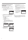
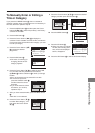
1 Press the Pause/Still button e on this VCR and then use
the Shuttle Ring f or Jog Dial g to search for the end of
the last previously recorded scene.
2 Press the REC/OTR button d to put it in the recording
pause mode.
3 Start playback on the source unit and search for the
point from which you want to record (copy) onto this
VCR.
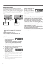
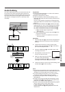
Assemble Editing
The assemble editing function makes it easy to record the
picture and sound of virtually any number of scenes or
programmes in succession.
Assemble editing from an external source, for example from a
video movie camera, can be performed in the same way.
Hints:
≥ The new sound is recorded on both the Hi-Fi audio tracks
and the normal audio track. The sound recorded on the
normal audio track is always in mono.
¡ If you want to change the audio recording level, adjust it.
(See page 20.)
Note:
≥ If you leave the VCR in the recording pause mode for more
than 5 minutes in step 2 or 5, the VCR automatically
switches over to the stop mode to protect the video heads.
Editing
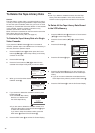
4 When that point is reached, press the Pause/Still button
e again to start recording the new picture and sound
from the playback unit.
5 To record (copy) additional scenes, press the Pause/Still
button e to put this VCR in the recording pause mode
and then perform steps 3 and 4 again.
6 At the point where you want to stop recording, press the
Stop button 9 to finish recording.
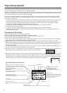
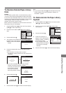
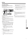
Recording unit (this VCR)
Front
k
l
Other VCR
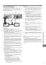
Preparations
≥ Connect a video movie camera or a VCR to this VCR with
an audio/video cable or a 21-pin Scart cable, as shown in
the illustration.
≥ Display the VCR picture on the TV.
≥ Insert the cassette on which the assemble editing is to be
performed, and make sure that its erasure prevention tab is
not broken out.
As soon as the cassette is inserted, the Cassette Number
Check starts. Wait a few moments until it is completed. (See
page 15.)
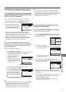
≥ Set the VCR/TV switch P to “VCR”.
≥ Press the INPUT SELECT button 3 to select the AV Input
(external input) “A1”, “A2” or “A3” according to the socket(s)
on the VCR to which the source unit has been connected.
A1: When connected to the AV1 21-pin Scart socket k
A2: When connected to the AV2 21-pin Scart socket l
≥ Make sure that “AV2” is set to “EXT”.
(See page 53.)
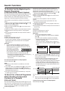
A3: When connected to the Video Input socket ] and
Audio Input sockets ^ on the front panel of the
this VCR
≥ Use the L connector for operations in the normal
(monaural) mode.
Video movie
camera
]
^
Rear