


11
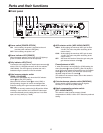
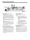
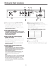
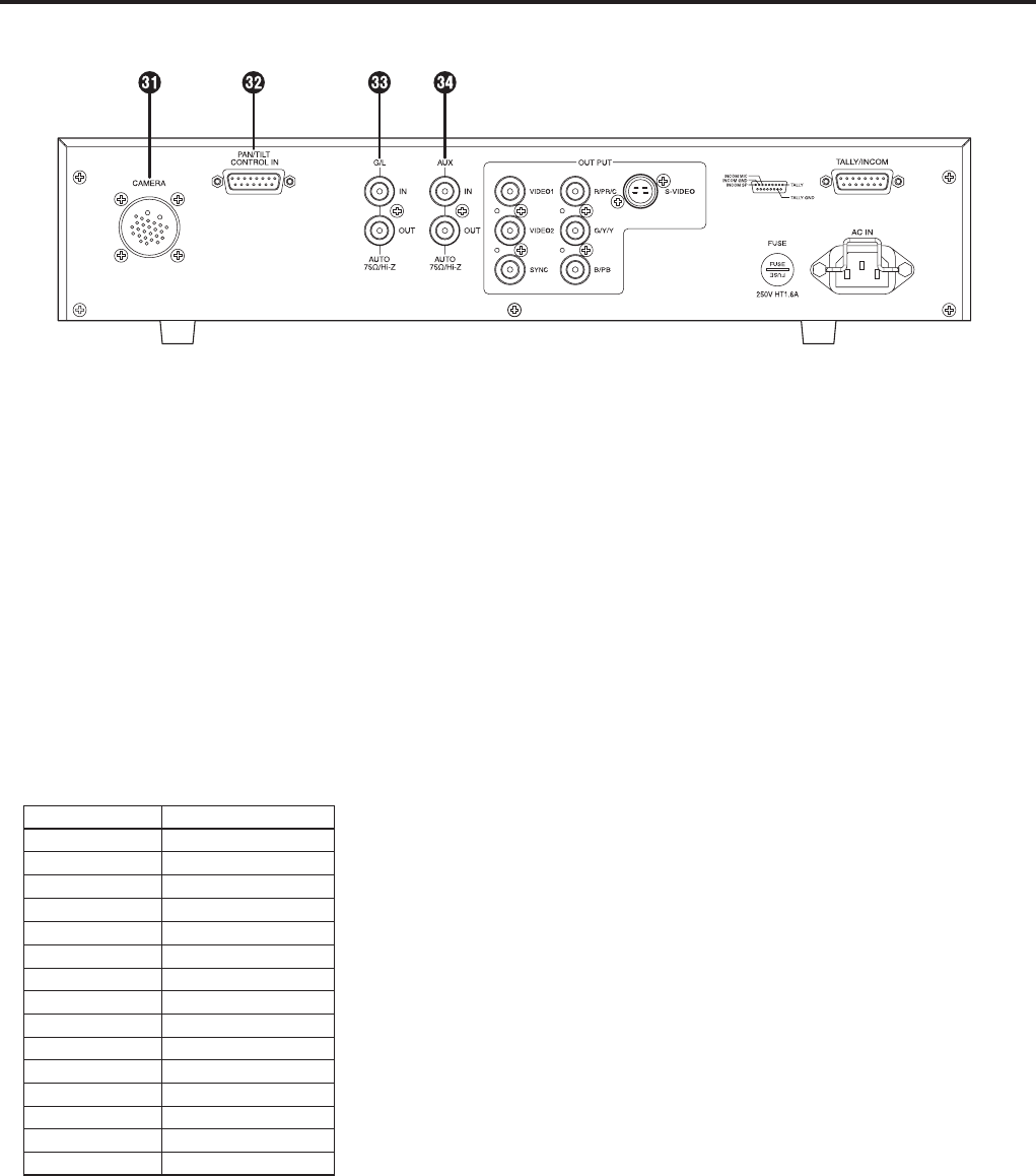
Camera cable connector [CAMERA]
(26-pin connector)
The camera’s cable (such as the AW-CA50A26) is
connected here.
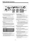
Contact-type pan/tilt head control connector
[PAN/TILT CONTROL IN]
(D-SUB 15-pin connector)
This has the same shape as the tally/intercom input/
output connector. Take care not to confuse the two
when connecting them.
A controller for controlling the lens (a lens with zoom
and focus servo) and pan/tilt head (up, down, left,
right, defroster, wiper, etc.) is connected here. (Only a
contact-type controller can be connected.)
Pin No. Signal Name
1 LEFT
2 RIGHT
3 UP
4 DOWN
5 FAR
6 NEAR
7 TELE
8 WIDE
9 DEFROSTER
10 WIPER
11 COMM
12 +5 V
13 +V (+7.5 V)
14 –V (+2.5 V)
15 GND
The optional board must be installed in the camera in
order to use a contact-type pan/tilt head. For details,
refer to the camera’s operating instructions.
When the control pins (#1 to #10) are connected to the
COMM pin (#11), the control signals are sent from the
RCU to the camera.
When the controller is to be fabricated, connect a
resistor with a resistance of 1 to 10 kilohms (1/8 W or
more) between the COMM pin and +5 V pin.
Ensure that both the LEFT and RIGHT pins are not
connected to the COMM pin at the same time.
Similarly, do not connect both the UP and DOWN, FAR
and NEAR or WIDE and TELE pins to the COMM pin
at the same time.
Pins #12 to #15 are used when exercising lens control
only. To do this, connect the controller’s FOCUS CONT
pin to NEAR (pin #6) and its ZOOM CONT pin to WIDE
(pin #8). (Normally, pins #12 to #15 are not used when
exercising control by contacts.)
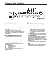
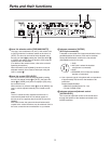
Gen-lock input/output connector
[G/L IN/OUT]
(75-ohm automatic termination)
The external sync signals (black burst signals or
composite signals) from another system are connected
here.
Note:
The input signals must be connected to the BNC
connector marked “IN” (75-ohm automatic termination).
If it is connected to the BNC connector marked “OUT,” a
high-impedance state will result, and the connector will
not be terminated by the 75-ohm resistance.
AUX signal input/output connector
[AUX IN/OUT] (75-ohm automatic termination)
Connect the line view signals from a live switcher or other
device here.
Note:
The input signals must be connected to the BNC
connector marked “IN” (75-ohm automatic termination).
If it is connected to the BNC connector marked “OUT,” a
high-impedance state will result, and the connector will
not be terminated by the 75-ohm resistance.
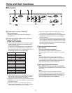
Parts and their functions
Rear panel