


TC-14A12P / TC-20B12
- 2 -
WARNING
This service information is designed for experienced repair technicians only and is not designed for use by the general public.
It does not contain warnings or cautions to advise non-technician individuals of potential dangers in attempting to service a product.
Products powered by electricity should be serviced or repared only by experienced professional technicians.
Any attempt to service or repair the product deal with in this service information by anyone could result in serious injury or death.
Contents
General Guidelines ..................................................................... 02
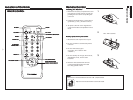
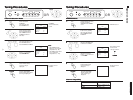
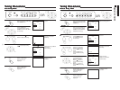
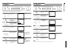
Operation Guide ......................................................................... 03
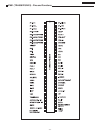
IC 601 - Pins and Functions ..................................................... 15
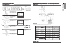
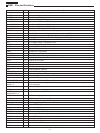
IC601 and IC451 Voltage Table ................................................ 17
IC601 - Block Diagram .............................................................. 18
General Summary .................................................................... 19
Service Adjustments and Calibrations
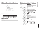
Service Mode .............................................................................. 20
How to operate the DAC controls ............................................. 20
EQUIPMENT REQUIRED .......................................................... 21
AGC RF CALIBRATION ............................................................. 21
BUZZ (SOUND CIRCUIT) .......................................................... 21
ANODE AND HEATER VOLTAGE CONFIRMATION ............... 21
PAL COLOR OUTPUT SIGNAL ADJUSTMENT ...................... 21
NTSC SUB-TINT CALIBRATION ............................................... 22
PROTECTION CIRCUIT (SHUTDOWN) ................................... 22
CONFIRMATION OF OPERATION ........................................... 22
WHITE QUALITY CALIBRATION .............................................. 22
VERTICAL DEFLECTION .......................................................... 22
CALIBRATION AND CONFIRMATION ...................................... 22
CRT CUT OFF CALIBRATION .................................................. 23
WHITE BALANCE CALIBRATION ............................................. 23
SUB-BRIGHTNESS CALIBRATION ........................................... 23
FOCUS CALIBRATION .............................................................. 23
COLOR PURITY ADJUSTMENT ............................................... 24
CONVERGENCE CALIBRATION ............................................... 24
EEPROM - Memory Maps ......................................................... 25
Power Source Voltages .............................................................. 25
Main Board Schematic Diagram ................................................ 26
CRT Board Schematic Diagram ................................................ 27
Main Board Conductor view ...................................................... 28
Waveform .................................................................................... 32
Parts Location ............................................................................. 35
Packing and Acessories ............................................................. 36
Replacement Mechanical Parts List .......................................... 36
Replacement Electrical Parts List .............................................. 37
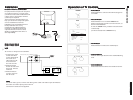
General Guidelines
An Isolation Transformer should always be used during the
servicing of a receiver whose chassis is not isolated from the AC
power line. Use a transformer of adequate power rating as this
protects the technician from accidents resulting in personal injury
from electrical shocks. It will also protect the Receiver from being
damaged by accidental shorting that may occur during servicing.
When servicing, observe the original lead dress, especially in
the high voltage circuit. Replace all damaged parts (also parts
that show signs of overheating.)
Always Replace Protective Devices, such as fishpaper, isolation
resistors and capacitors, and shields after servicing the Receiver.
Use only manufacturers recommended rating for fuses, circuit
breakers, etc.
High potentials are present when this Receiver is operating.
Operation of the Receiver without the rear cover introduces
danger from electrical shock. Servicing should not be performed
by anyone who is not thoroughly familiar with the necessary
precautions when servicing high-voltage equipment.
Extreme care should be practiced when Handling the Picture
Tube. Rough handling may cause it to implode due to
atmospheric pressure (14.7 lbs per sq. in). Do not sick or scratch
the glass or subject it to any undue pressure. When handling,
use safety goggles and heavy gloves for protection. Discharge
the picture tube by shorting the anode to chassis ground (not to
the cabinet or to other mounting hardware). When discharging,
connect cold ground (i.e. dag ground lead) to the anode with a
well insulated wire or use a grounding probe.
Avoid prolonged exposure at close range to unshielded areas of
the picture tube to prevent exposure to X-ray radiation.
The Test Picture Tube used for servicing the chassis at the bench
should incorporate safety glass and magnetic shielding. The
safety glass provides shieldinf for the tube viewing area against
X-ray radiation as well as implosion. The magnetic shield limits
X-ray radiation around the bell of the picture tube in addition to
restricting magnetic effects. When using a picture tube test jig
for service, ensure that the jig is capable of handling 31kV without
causing X-ray radiation.
Before returning a serviced receiver to the owner, the service
technician must thoroughly test the unit to ensure that is
completely safe to operatore. Do not use a line isolation
transformer when testing.