


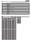

- 21 -
TC-14A12P / TC-20B12
Service Adjustments and Calibrations
TEST EQUIPMENT
To do all of these electrical adjustments, the following equipment
is required:
• Dual-Trace Oscilloscope
Voltage Range: 0.001 V to 50 V/Div.
Frequency Range: DC to 50 MHz
Probes: 10:1, 1:1
• NTSC Video Pattern Generator
• DVM (Digital Volt Meter)
• MTS/SAP Signal Generator
• (TV Multi-Channel Sound Modulator (U.S.A.))
• Plastic Tip Driver and Non-Metal Driver
• Isolation Transformer (Variable)
• Degaussing Coil
• White Pattern Generator
• Audio Generator
AGC RF CALIBRATION
1. PREPARATION:
1.1. Receive a color bar pattern and assure a RF input signal of
75Ω opened, channel 13 (211.25 MHz).
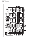
1.2. Connect the digital multimeter in TPA 15.
2. CALIBRATION:
2.1. Select the option “RF AGC” in the “CHK2” service mode.
2.2. Adjust RF AGC to 2.2±0.1V in TPA20.
3.3. Increase the input level by +2 dB and confirm that the voltage
decrease.
Tuner ENV56D75G3R TEDH9-301A
Level 69dB mV 69dB mV
VIF DETECTOR OUTPUT LEVEL CONFIRMATION
1. CALIBRATION:
1.1. Install the chassis in the VIF calibration JIG and receive a
color bar pattern with 63 dBU (75Ω opened).
1.2. Connect the oscilloscope to TPA33.
1.3. Confirm that the video output signal is within a range of 1.05
± 0.15 Vp-p in TPA33.
BUZZ (SOUND CIRCUIT)
1. PREPARATION:
1.1. Connect the oscilloscope with a 7kHz filter between TPA41
and ground or between the speaker’s terminals
1.2. Adjust the sound volume to the maximum.
1.3. Set “TONE” to “NORMAL” and “AVL” turned off.
2. CONFIRMATION:
2.1. Receive a color bar pattern channel 2, with local frequency
adjusted and the AFC turned on (Channel with sound bearer and
without modulation).
2.2. Assure that the width in the buzzing waveform is smaller than
500 m Vp-p.
ANODE AND HEATER VOLTAGE CONFIRMATION
1. PREPARATION:
1.1. Receive a crosshatch pattern.
2.2. Adjust the bunch current in zero. (0 beam)
3.3. Adjust “SCREEN VR” and “CONTRAST” to minimum.
2. CONFIRMATION:
2.1. Connect a voltage meter between TPA12 and ground. Confirm
that the voltage +B is within a range of 140.5V± 1.5V
2.2. Connect a high frequency voltage meter (VRMS.) among the
heater, and confirm that the reads tension is within a range of 6.3
± 0.24 (VRMS)
2.3. Connect the high voltage meter in the CRT anode pin, and
confirm that the high voltage is within a range of [A]:
• TC-14A12P [A]=24.5 +0.7kV
_
1.5kV
• TC-20B12 [A]=26.5 +0.7kV
_
1.5kV
PAL COLOR OUTPUT SIGNAL ADJUSTMENT
1. PREPARATION:
1.1. Receive a color bar pattern and adjust the local frequency.
1.2. Adjust “IMAGE” to DYNAMIC NORMAL, “CONTRAST” to 63
and “SUB-CONTRAST” to 21.
1.3. Adjust the “COLOR FOR CHANNEL” level to NORMAL.
1.4. Set the CHK2 service mode option, press “5” on the remote
control unit and confirm that OSD becomes blue (AKB turned off).
1.5. Connect a short circuit jumper between TPA10 and TPA20.
1.6. Adjust [A] for 2.3 ± 0.2V through the BRIGHT control variation
in the test point TPL2.
1.7. Fix G-DRIVE GAIN, R-DRIVE GAIN and B-DRIVE GAIN data
in 1FH or 31 DAC.
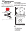
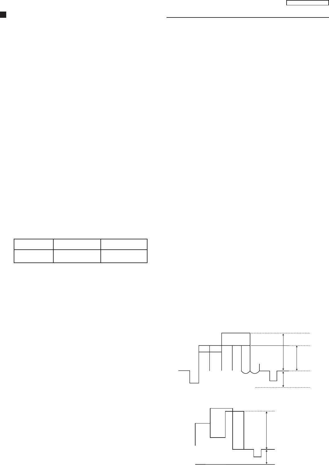
2. CALIBRATION:
2.1. Connect the oscilloscope in TPL2 (G-OUT) with a 10KΩ
resistor and adjust “CONTRAST”, so that the waveform in [B] it is
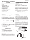
of 2.6±0.1V according to fig. 1.
2. Adjust “SUB-COLOR” to obtain 2,45±0.1V in [D] according to
fig. 1.
3. Connect the oscilloscope in TPL1 (R-OUT) a 10KΩ resistor in
and confirm that the waveform in [C] it is of 2.45±0.1V according
to fig. 2.
4. Remove the jumper between TPA10 and TPA20, press “5” and
confirm that OSD becomes white (AKB turned on).
A=2.3±0.2Vp-p
BD
Fig. 1
A=2.3±0.2Vp-p
C
Fig. 2