


- 19 -
TC-20G12P / TC-29G12P / TC-29G12PU
Service Adjustments and Calibrations
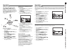
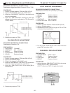
AFT ADJUSTMENTS
REQUIRED EQUIPMENTS / CONNECTIONS:
Digital Voltmeter, C.W. generator (45.75 Mhz) and VIF
HEAD.
PREPARATION:
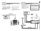
1. Disconnect antenna.
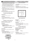
2. Connect the generator at TP37, using VIF HEAD.
3. Connect a jumper between TP8 (RF AGC) and GND.
4. Connect the Voltmeter between TP16 (AFT) and GND.
5. Turn On the TV.
PROCEDURE:
1. Adjust AFT (DAC: C9) to 128.
2. Adjust the AFT coil (L167) until the Voltmeter on TP16
show 2.5±0.1V.
3. Turn On the generator, and move the output signal
between 45,650Mhz and 45,850Mhz. Check the Voltmeter
on TP16 must be indicate a variation biggest 0.4V.
4. Remove the jumper, disconnect the Voltmeter and THE
CW Generator.
Note: To C.W.Generator the standard frequency is
45,75Mhz, the signal TV level is 90dBµV to 75O.
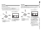
+B VOLTAGE VERIFICATION
REQUIRED EQUIPMENTS / CONNECTIONS:
Digital Voltmeter (+): according relation below.
(
_
): GND (HOT)
PROCEDURE:
1. Adjust BRIGHT and CONTRAST control until get a totally
black screen.
2. Do the medition relationed below:
3. Return the BRIGHT and CONTRAST adjusts to the
normal image.
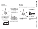
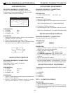
RF AGC ADJUSTMENT
REQUIRED EQUIPMENTS / CONNECTIONS:
Digital Voltmeter: TP8 the AGC Tuner terminal.
PROCEDURE:
1. Apply a COLOUR BAR pattern of 63±2dB (75Ω open)
in the antenna terminal.
(Using a high VHF channel 7 ~ 13).
2. Confirm a normal image.
3. Check if the noises disappear when the RF AGC register
(DCA:Ca) is decreased and note the reference voltage.
Confirm if the noise appear when the register is
increased.
4. Increase slowly the AGC register (DAC: Ca) until the
TP8 voltage get a reference voltage less of 0.2V
(maximum voltage)
5. Check if the RF AGC voltage (reference voltage) falls
more then 0.3V when the input is increased 2dB.
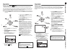
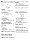
IF DETECTOR OUTPUT ADJUSTMENT
REQUIRED EQUIPMENTS / CONNECTIONS:
Oscilloscope: Connect to TP12.
PROCEDURE:
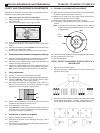
1. Apply a COLOURBAR pattern of 100IRE level.
2. Adjust the output detection (DAC:Ce) (including the
SYNC signal) inside of 1.0 ±0.1Vpp range
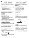
3. Check if the SYNC amplitude signal (SYNC S & output
detection P ratio) is inside of 30±5% range.
Note: The RF signal ratio modulation is 87.5% ~ 90%.
SUB-CONTRAST ADJUSTMENT
PREPARATION:
1. Picture MenU DYNAMIC
2. CONTRAST Max. or Normal
3. BRIGHT Center or Normal
4. SHARPNESS Center or Normal
5. COLOR Center or Normal
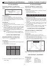
Tuner IF
Tuner
VIF HEAD
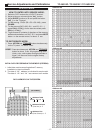
CHANNEL
MHz
7
175,25
8
181,25
9
187,25
10
193,25
11
199,25
12
205,25
13
211,25
S / (S+P) = 30%±5
P =
1.0Vpp
S
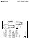
VOLTMETER (+)
C865(+)
TP29
TP30
C859(+)
TP5
TP34
TP11
C861
20 inches
130VDC
24V±2VDC
13V±2VDC
18V±2VDC
9V±0,5VDC
200±15VDC
5±0,25VDC
12,5±0,5VDC
29 inches
130VDC
27,4V±2VDC
13V±2VDC
18V±2VDC
9V±0,5VDC
220±15VDC
5±0,25VDC
12,5±0,5VDC