


- 21 -
TC-20G12P / TC-29G12P / TC-29G12PU
Service Adjustments and Calibrations
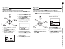
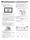
AUDIO OUTPUP LEVEL VERIFICATION
REQUIRED EQUIPMENTS / CONNECTIONS:
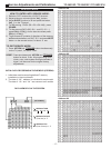
JIG Filter: TP18.
RF signal generator: RF antenna input.
RMS Voltmeter: Between JIG Filter and GND.
PROCEDURE:
1. Apply the next signals on the antenna input:
Video: 100 IRE Flat Field, 30% modulation.
Audio: 300Hz, 100% modulation, mono
(70±5dB, 75Ω open, P/S 10dB)
2. Check the Audio level to the
RMS Voltmeter show 150 mVrms.
MTS CIRCUIT ADJUSTMENT
The MTS Circuit adjust of BR2L chasis, is doing through
four steps:
1. VCO Stereo adjustment.
2. Filter adjustment.
3. Input level adjustment.
4. Stereo separation adjustment.
Note: The adjustment must be done in the sequence
showed before. VIF, TP12 (Level Detector) must be
adjusted before MTS adjustment.
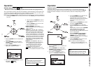
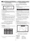
STEP 1 VCO STEREO ADJUSTMENT
REQUIRED EQUIPMENTS / CONNECTIONS:
1KΩ resistive jumper: Connect between the TP14 and GND.
22µF 16V capacitive jumper: Connect between the TP18
(MPX in). and GND.
Frequency Counter: Connect between the TP22 (R-OUT) and
GND.
PROCEDURE:
1. Remove the antenna.
2. On the service mode, select DAC: M1
3. Adjust MTS STEREO PLL VCO DAC: M1 until the
frequency counter show 15.734KHz±50Hz.
(15.684~15784KHz).
Note: The TV must be turn ON minimum 15 minutes before
adjustment.
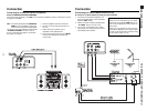
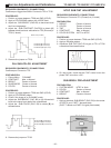
STEP 2 FILTER ADJUSTMENT
REQUIRED EQUIPMENTS / CONNECTIONS:
RF Generator: Antenna input (RF)
Oscilloscope: Between TP21 (L-out) and GND.
RMS meter: Between TP18 (MPX-in) and GND.
Note: The GND of oscilloscope must be next of IC2201-01
terminal for minimum noise.
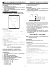
+60
_
30
PROCEDURE:
1. Apply the next signal to antenna input ( RF):
Video: 100 IRE Flat Field, Modulation 30%.
Audio: 15.734KHz sinusoidal wave.
(70±5dB, 75Ω open, P/S 10dB).
2. Adjust the output level signal generator for that a
15.734KHz wave form be 100 ±5mVrms on TP18.
3. On service mode, adjust DAC: M2.
4. Adjust MTS filter (DAC:M2) until the wave form
amplitude, on oscilloscope screen be minimum.
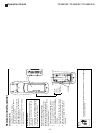
STEP 3 INPUT LEVEL ADJUSTMENT
REQUIRED EQUIPMENTS / CONNECTIONS:
JIG Filter: Connect to TP22.
RF generator: Connect to RF input antenna terminal.
RMS meter: Between JIG Filter and GND.
PROCEDURE:
1. Apply the next signal on antenna input ( RF):
Video: 100 IRE Flat Field, Modulation 30%.
Audio: 300 Hz, modulation 100%, mono.
(70±5dB, 75Ω open, P/S 10dB).
2. On service mode, adjust DAC: M0
3. Adjust the input level MTS (DAC: M0) until the Voltmeter
show 212 ± 10.5mVrms.
STEP 4 STEREO SEPARATION ADJUSTMENT
REQUIRED EQUIPMENTS / CONNECTIONS:
RF generator: Antenna input (RF).
Oscilloscope: Between TP22 (R-out) and GND.
PROCEDURE:
1. On audio MENU set STEREO.
2. Apply the next signal on antenna input ( RF):
Video: 100 IRE Flat Field, Modulation 30%.
Audio: 300 Hz, modulation 100%, stereo (L channel)
(70±5dB, 75Ω open, P/S 10dB).
3. Adjust the low level separation (DAC: M3) until the wave
form amplitude on the oscilloscope screen, be minimum.
4. Adjust the audio of RF generator to 3KHz.
5. Adjust the high level separation (DAC: M4) until the wave
form amplitude on the oscilloscope screen, be minimum.
6. Repeat steps 2 to 4.
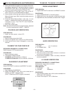
TP18
TP22