


- 22 -
TC-20G12P / TC-29G12P / TC-29G12PU
Service Adjustments and Calibrations
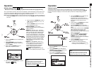
HUM VERIFICATION
REQUIRED EQUIPMENTS / CONNECTIONS:
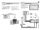
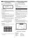
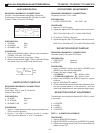
JIG filter: Connect between the speakers terminals.
Oscilloscope: Connect between the JIG Filter and GND.
Function Tester: Connect to PC-Board.
PREPARATION:
1. VOLUME Max.
2. AI SOUND OFF
3. SPEAKER SW ON
PROCEDURE:
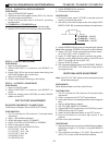
1. Apply a COLORBAR pattern without audio modulation
(70±5dB, 75Ω open, P/S 10dB)
2. Check if the hum level is less then 1.5Vp-p
3. When the hum level be bigger 1.5Vp-p, use the JIG filter
and check if the hum level is less that 0.5Vp-p
AUDIO OUTPUT CHECK UP
REQUIRED EQUIPMENTS / CONNECTIONS:
RMS Voltmeter:
Input Cable: VAO L and R Terminals.
Ground Cable: GND.
PREPARATION:
1. VOLUME Maximum
2. AI SOUND OFF
3. SPEAKER SW OFF
PROCEDURE:
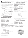
1. Apply a 7.5KHz standard audio signal modulated with
1KHz, and 30% deviation.
2. Check if the RMS Voltmeter shows a voltage
430±150mVrms between L and R terminals.
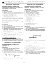
HUM
level
SYNTHETIZER ADJUSTMENTS
REQUIRED EQUIPMENTS / CONNECTIONS:
Frequency Counter: TP42 GND
PREPARATION:
1. CLOCK CORRECTION 128 (DAC: S0)
PROCEDURE:
1. Measure TP42 for period.
2. Adjust the register (DAC:S0) based in the next formula:
(DAC: S0)=128+0.901x10
6
{1-1/(244.1406xTP42)}
3. Or measure TP42 for frequency.
4. Adjust the register (DAC: S0) based in the next formula:
(DAC: S0) =128+0.901x10
6
{(244.1406-TP42)/244.1406}
DEFLECTION CIRCUIT CHECKUP
REQUIRED EQUIPMENTS / CONNECTIONS:
Voltmeter (50KV): Connect to CRTanode.
PREPARATION:
1. CONTRAST Minimum
2. BRIGHT Minimum
PROCEDURE:
1. Apply a BRIGHT pattern and adjust SCREEN and
BRIGHT until the back-line disappear
2. Check if the high voltage is [A].
TC-20G12P [A] = 26,25±1,25kV
TC-29G12P/TC-29G12PU [A] = 29,25±1,25kV
3. Return the SCREEN and BRIGHT adjust to original
positions.
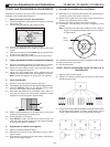
4. Apply a CROSSHATCH pattern.
5. Check exist vertical and horizontal lines distortions when
the user contrast adjust is on the maximum , while the
black level is optimized with the crosshatch bright signal.
DEFLECTION CIRCUIT ADJUSTMENT
The deflection circuit adjust of chassis BR1L/BR1D is done
in four steps:
1. H-CENTER
2. H-WIDE
3. V-HEIGTH
4. V-CENTER
STEP 1 H-CENTER ADJUSTMENT
PROCEDURE:
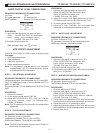
1. Apply a MONOSCOPE pattern.
2. Adjust CONTRAST on maximum, and BRIGHT on center.
3. Adjust the horizontal center (DAC:Cc) to center PHILIPS
pattern on the CRT.
(+)
(
_
)
SPK terminals
3.3mH 3.3mH
0.3µF
150Ω
(+)
(
_
)
Osciloscope
JIG filter