


- 25 -
TC-20G12P / TC-29G12P / TC-29G12PU
Service Adjustments and Calibrations
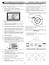
PURITY AND CONVERGENCE ADJUSTMENTS
Adjustment is necessary only if the CRT or the deflection yoke is
replaced or if the setting was disturbed.
1. When the Yoke or the CRT are substituted:
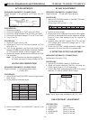
1.1- Position the deflexion yoke and the convergence ring at the
neck of the CRT.
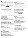
1.2- Position the convergence ring as figure below:
1.3- Turn on the TV set and tune on a red pattern
1.4- Position the deflection coil to obtain an uniform red at the
screen.
1.5- Enter service mode and press RECALL at the remote control
to begin purity adjustment mode.
1.6- Leave the set heating up for 30 seconds at white screen.
2. Primary adjustment of estatic convergence (centering)
2.1- Connect a crosshatch generator to the set and tune in signal.
Observe misconvergece at center of the screen only.
2.2- Adjust the 4 pole magnet (center rings); separate tabs and
rotate to converge blue with red.
2.2- Adjust the 6 pole magnet (rear rings); separate tabs and
rotate to convergence blue and red (magenta) with green.
Note: Precise convergence at this point is not important.
3- Purity Adjustment
3.1- Position TV set with screen pointed to the east
3.2- Fully degauss the receiver by using an external degaussing coil.
3.3- Press the RECALL button on the Remote Control again
until the Purity Check (red screen) appears.
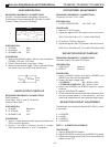
3.4- Move away the deflection coil and adjust rings 1 and 2 in a
way that the red portion stay exactly centered in equal
proportions to blue and green. (figure below):
3.5- Slowly move the deflection coil forward until an uniform red
is obtained completing the whole screen.
3.6- Fix the deflection coil in place
3.7- Keep RECALL button pressed at the remote control and
verify the purity of colours green, blue and white. Recheck
for purity and readjust if necessary.
4- Adjustment of estatic convergence
4.1- Apply a crosshatch standard signal.
4.2- Overcome the red line to blue adjusting the rings 1 and 4
(adjust center).
4.3- Overcome the red and blue lines with green adjusting the
rings 5 and 6 (adjust center).
5- DYNAMIC CONVERGENCE ADJUSTMENT
5.1-Move the DY on a horizontal and vertical way simultaneously,
to obtain a perfect side colour overcome.
5.2-Adjust the DY position for the image to stay symmetrical in
relation to the geometry of the screen.
5.3-Position the rubber parts to keep the DY in place.
5.4-If necessary, use permalloy to correct convergence on the
corners.
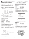
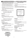
Note:To position the rubber parts (skids) to the DY, keep an
angle of 120 degrees between each part as is shown
on figure below:
5.5- If necessary use permalloy to correct convergence on the corners.
5.6-Put procedure 3.7 into action.
5.7-Exit Service Mode.
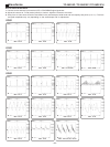
VERIFY PURITY ADJUSTMENT WITH THE HELP OF A
MICROSCOPE
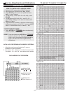
1- Apply a white standard signal.
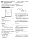
2- Using a microscope, observe the pixel with a correct format,
adjust the purity rings.
3- Using a microscope, observe the pixel on the sides of the screen
and compare figure below. To obtain a pixel with a correct
format, adjust the deflector coil moving forward and back.
Green
Blue
Red
Skids
(rubber)
120
°°
°°
°
120
°°
°°
°
120
°°
°°
°
Purity Rings
Centered
Over G3/G4 Gap
6 pole rings
4 pole rings