


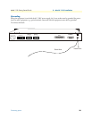
Connecting E1 links 28
Model 1195 Getting Started Guide 3 • Model 1195 installation
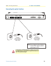
Connecting E1 links
Connect E1 line after ensuring that transmission device have been grounded. A Bit Error Rate (BER) test may
be conducted on E1 Link using a BERT tester to ensure that the E1 errors are within the permitted limits /
threshold.
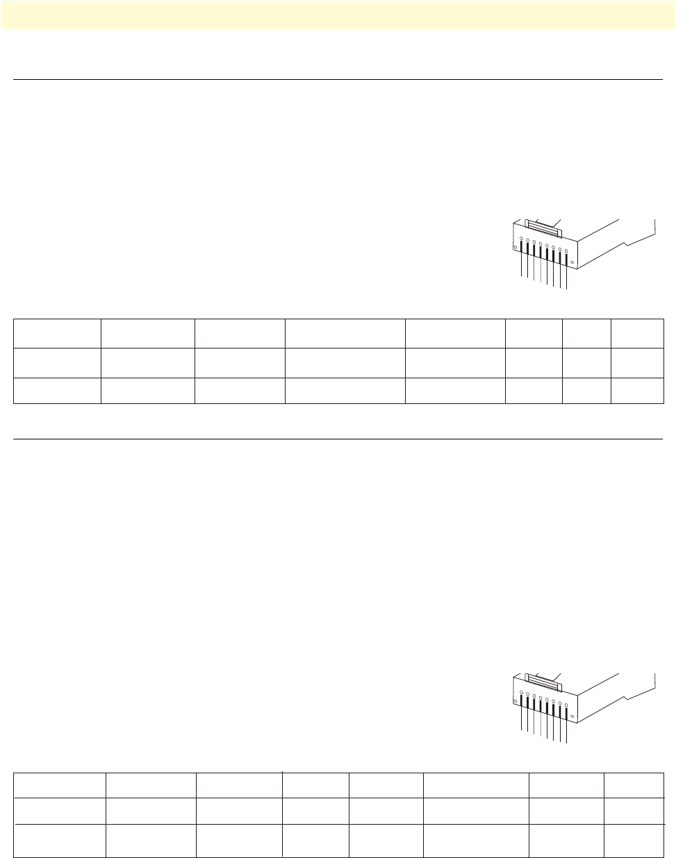
Definition for E1 Interfaces
The E1 Interface (RJ-45 connector) is defined as:
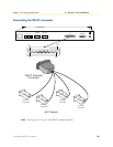
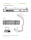
Connecting Ethernet Links
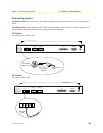
Please configure the Ethernet port of the equipment at both sides as well as the Ethernet Ports of the devices
that are connected to the equipment. Connect the Ethernet links.
Please ensure that the connecting LANs on both sides of the link are operating in the same IP domain.
Verifying the connection
Ping over the Ethernet connection from one side to the other (near-end to the far-end) to verify the link.
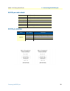
Definition for Ethernet Interfaces
The Ethernet Interface (RJ-45 connector) is defined as:
1 2 3 4 5 6 7 8
Rx+ Rx- N/C Tx+ Tx- N/C N/C N/C
Data In + Data In - Data Out + Data Out -
1
2
3
4
5
6
7
8
1
2
3
4
5
6
7
8
1 2 3 4 5 6 7 8
Tx+ Tx- Rx+ N/C N/C Rx- N/C N/C
Data Out+ Data Out- Data In+ Data In-