


AAPPPPEENNDDIIXX EE
PATTON K MODULE JUMPER SETTINGS
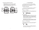
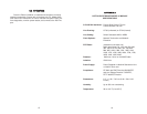
Figure C (below) shows the top view of the IM1/K printed circuit
board (PCB) and the location of the jumpers.
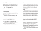
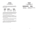
Figure D (below) shows the top view of the IM2RC/K printed circuit
board (PCB) and the location of the jumpers.
Figure C. K Module, top view, showing location of jumpers
Interface Panel
Edge Connectors
ON
JP5
JP4
ON
12345678
OFF
JP1
JP6
JP3
JP7
20
1 2 3 4 5 6 7 8
Figure D. IM2RC/K, top view, showing location of jumpers
JP5
JP4
JP6
JP7
JP9
JP3
Front
Panel
Rear
ON
12345678
OFF
ON
DIP Switches
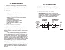
AAPPPPEENNDDIIXX DD
PATTON K MODULE
DIP SWITCHES
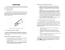
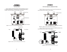
Figure A (below) shows the location of the DIP switches on top of
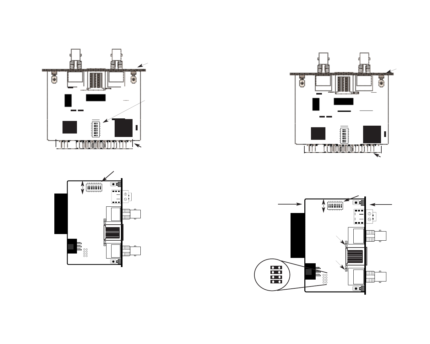
the printed circuit board. Following Figure A, Figure B shows the ori-
entation of the DIP switches on the printed circuit board.
Figure A. IM1/K top view, showing location of DIP switches
Interface Panel
Edge Connectors
DIP Switches
ON
JP5
JP4
ON
12345678
OFF
JP1
JP6
JP3
JP7
19
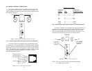
Figure B. IM2RC/K, top view, showing location of DIP switches
1 2 3 4 5 6 7 8
Front Panel
Rear
DIP Switches
ON
12345678
OFF
ON