


13 14
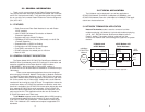
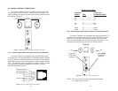
5.3 MAKING INTERFACE CONNECTIONS
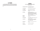
The Patton K Module may be connected to G.703/G.704 ports
using a single 120 ohm RJ-48C or a dual 75 ohm coax (BNC). The
Patton K Module rear panels and the location of these connectors are
show below in Figure 4.
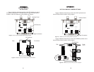
The Patton K Module is equipped with a single RJ-48C jack for
connections to a 120 ohm twisted pair G.703/G.704 network interface.
If your G.703/G.704 network terminates via RJ-48C, use the diagram
below and the table on the following page to make the proper connec-
tions. The connector pinout and signals are shown in Figure 5, below.
Use the following connection diagram to connect the 120 ohm
G.703/G.704 network channel.
RJ-48C Cable (8-Wire)
K Module G.703/G.704
SIGNAL
PIN# NETWORK SIGNAL
RX+ 1-----------------------TX+
RX- 2-----------------------TX-
TX+ 5-----------------------RX+
TX- 4-----------------------RX
Shield 3-----------------------Shield
Shield 6-----------------------Shield
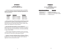
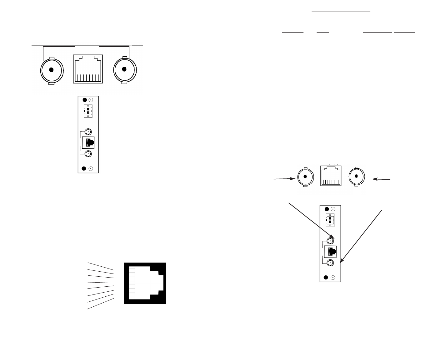
The Patton K Module is also equipped with dual female BNCs (TX
and RX) for connection to a 75 ohm dual coax G.703/G.704 network
interface. If your G.703/G.704 network terminates via dual coaxial
cable, use the diagram below to make the proper connections. The
connector pinout and signals are shown in Figure 6, below.
NOTE: The outer conductor of the coax cables are isolated
from system earth ground.
Figure 4: K Module Rear Panels, Showing Location of Connectors
RX
(Data
FROM
G.703/G.704
Network)
TX
(Data
TO
G.703/G.704
Network)
Figure 6: 75 ohm Dual Coaxial G.703 Interface
Network
TX
RX
Figure 5: 120 ohm RJ-48C G.703/G.704 Interface
(No Connection) 8
(No Connection) 7
(No Connection) 6
(TX+) 5
(TX-) 4
(No Connection) 3
(RX-) 2
(RX+) 1
8
7
6
5
4
3
2
1
RX
TX
Network
Network
5.3.1 Connect Twisted Pair (120 ohm) to G.703/G.704 Network
5.3.2
Connect Dual Coaxial Cable (75 ohm) to G.703/G.704 Network
Line
TX
RX
Network
Line
TX
RX