


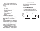
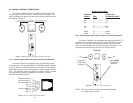
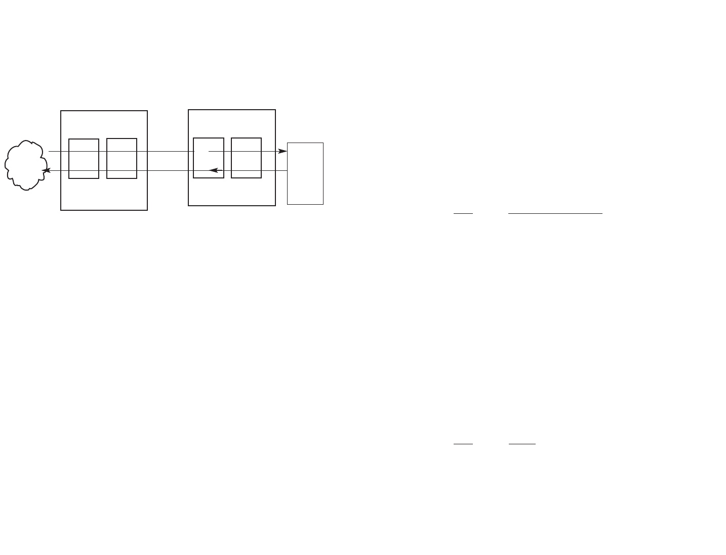
3.2 NETWORK EXTENSION APPLICATION
Network Extension mode is used to extend nx64 -2.048Mbps
G.703/G.704 service across a DSL link, providing an nx64
G.703/G.704 link at the remote site. Transmitter clocking is
derived from the G.703/G.704 network, and transmitted over the
baseband modem link (refer to Figure 2, below).
7
Figure 2. Clock Settings in a Network Extension Application
nx64kbps
G.703/G.704
Network
nx64kbps
G.703/G.704
CPE
K Module
K Module
1095
(1095RC)
1095
(1095RC)
Cable Span
K Module and
mDSL Modem
K Module and
mDSL Modem
Clock/
Data
Clock/
Data
Clock/
Data
Clock/
Data
External
Clocking
External
Clocking
set to Force CP
8
4.0 CONFIGURATION
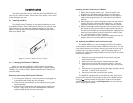
The K Module features configuration capability via hardware
switches and jumpers. Sections 4.1 and 4.2 describe all switch and
jumper configurations for the Patton K Module. Section 4.3 describes
the configuration required for your mDSL modem.
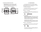
4.1 DIP Switch Configuration
The K Module has eight internal DIP switches (S1-1 through S1-8).
The DIP switches can be configured as either “On” or “Off.” See
Appendix D for location and orientation of the DIP switches.
Switch S1-1: Line Coding
Use Switch S1-1 to control the Network Line Coding options. Set
these options to be the same as the Line Coding that has been provid-
ed by your Service Provider.
S1-1 Line Framing & Coding
Off HDB3
On AMI
Line Coding Options:
High Density Bipolar 3 (HDB3): In HDB3 coding, the transmitter
deliberately inserts a bipolar violation when excessive zeros in the
data stream are detected. The receiver recognizes these special
violations and decodes them as zeros. This method enables the
network to meet minimum pulse density requirements. Use HDB3
unless AMI is required in your application .
Alternate Mark Inversion (AMI): AMI coding does not inherently
account for ones density. To meet this requirement, you should
ensure that the data inherently meets pulse density requirements.
Switch S1-2 : CRC-4 Multiframe
CRC-4 Multiframe uses Time Slot zero to carry CRC-4 information.
When CRC-4 is enabled (ON), the unit synchronizes to the CRC-4
multi-frame protocol.
S1-2 Option
Off Disabled
On Enabled
NOTE: When the data rate is set to 2048 Kbps, K Module trans-
mits user data on all 32 timeslots, ignoring framing information. In
this case, Switch S1-2 will be ignored.