


9 of 33
ISSUED: 09-20-06 SHEET #: 202-9167-3 01-26-07
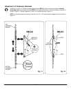
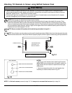
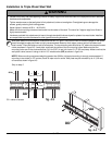
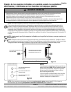
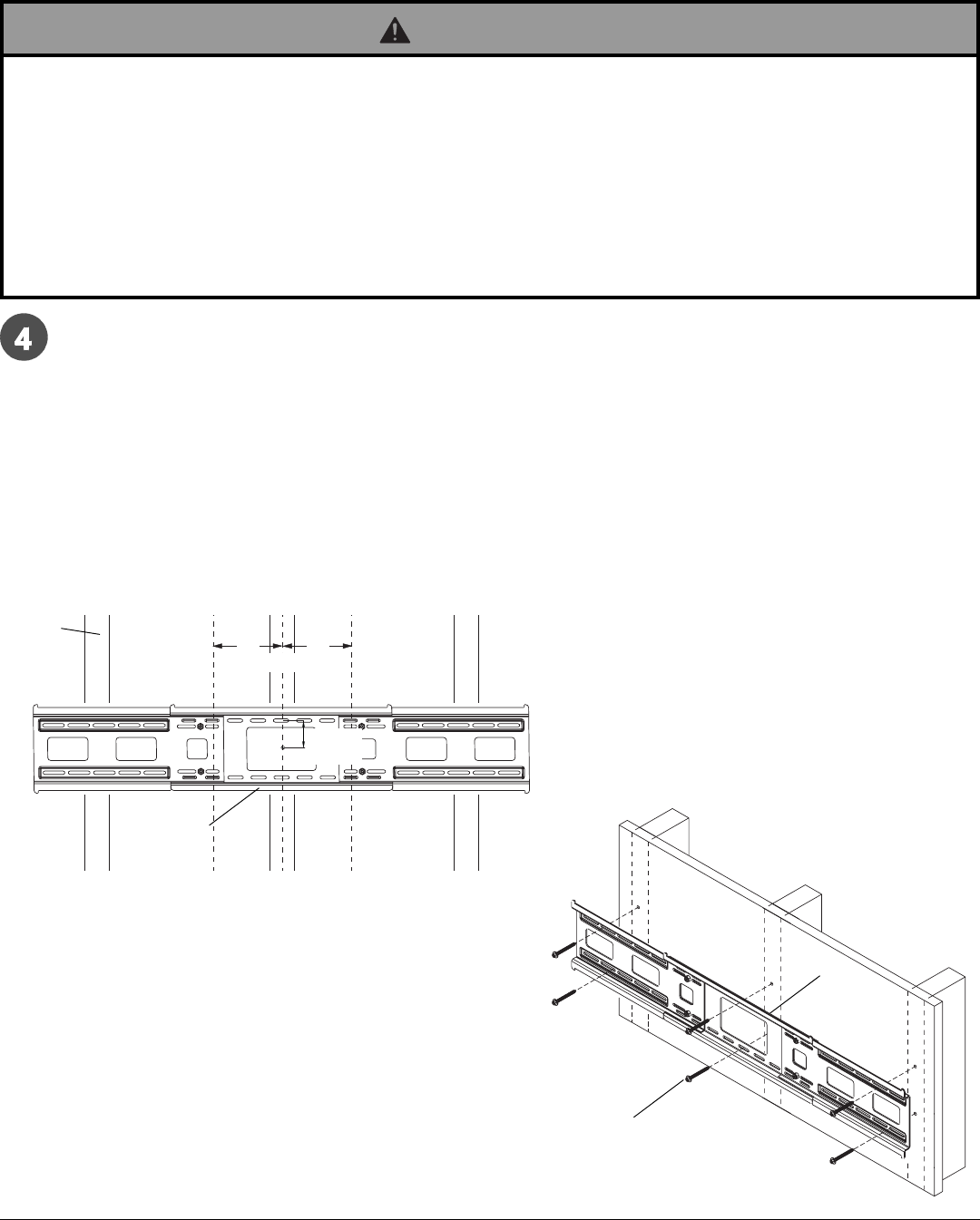
Installation to Triple Wood Stud Wall
fig. 4.3
CS = center of screen
4"
(102 mm)
4"
(102 mm)
Wall plate (AA) can be mounted to three studs that are 16" apart. Use a stud finder to locate the edges of the studs.
Use of an edge-to-edge stud finder is highly recommended. Based on their edges, draw a vertical line down each
stud’s center. Place wall plate on wall as a template. The top mounting slots should be 2.5" above the desired screen
center as shown in figure 4.3. Level plate, and mark the center of the six mounting holes. Make sure that the
mounting holes are on the stud centerlines. Drill six 5/32" (4 mm) dia. holes 2-1/2" (65 mm) deep. Make sure that the
wall plate is level, secure it using six #14 x 2.5" wood screws (DD) as shown in figure 4.4.
NOTE: When mounting equipment weighing greater than 200 lbs, triple stud mounting is strongly recommended. If
mounting to two studs on 16" centers, leave an open stud in center. Wall plate may be mounted up to 4" (102 mm)
off-center as shown in figure 4.3.
Skip to step 5.
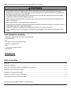
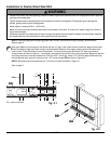
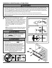
• Installer must verify that the supporting surface will safely support the combined load of the equipment and all attached
hardware and components.
• Tighten wood screws so that wall plate is firmly attached, but do not overtighten. Overtightening can damage the
screws, greatly reducing their holding power.
• Never tighten in excess of 80 in. • lb (9 N.M.).
• Make sure that mounting screws are anchored into the center of the stud. The use of an "edge to edge" stud finder is
highly recommended.
• Hardware provided is for attachment of mount through standard thickness drywall or plaster into wood studs. Installers
are responsible to provide hardware for other types of mounting situations.
WARNING
2.5"
(64 mm)
CS
DD
AA
fig. 4.4
AA
STUD